Metal stamping equipment

A metal stamping and equipment technology, applied in the field of metal stamping, can solve problems such as affecting the stamping efficiency of stamping equipment, inconvenient collection of stamped products, and unfavorable centralized processing of stamped products, etc., to achieve mass production, high stamping efficiency, and improved service life Effect

Inactive Publication Date: 2020-06-16
严白双
View PDF0 Cites 1 Cited by
  • Summary
  • Abstract
  • Description
  • Claims
  • Application Information

AI Technical Summary

Problems solved by technology

[0002] Metal gaskets are refined from high-precision, high-hardness sheet materials. They are usually used in the adjustment and measurement of precision molds or precision hardware, or as spacers, and become precision gaskets, sometimes called mold gaskets or precision gaskets. Gap sheets and metal gaskets are generally stamped by a stamping machine. The metal sheet is sent to the bottom of the stamping machine and pressed under the action of a mold. The existing metal stamping equipment is not convenient for collecting stamped products, which is not conducive to stamping The centralized processing of products affects the stamping efficiency of stamping equipment, so it is urgent to develop a metal stamping equipment to solve the above problems and facilitate market promotion and application

Method used


Image

  • Metal stamping equipment
  • Metal stamping equipment
  • Metal stamping equipment

Examples


Embodiment Construction

[0020] The following will clearly and completely describe the technical solutions in the embodiments of the present invention with reference to the accompanying drawings in the embodiments of the present invention. Obviously, the described embodiments are only some, not all, embodiments of the present invention. Based on the embodiments of the present invention, all other embodiments obtained by persons of ordinary skill in the art without making creative efforts belong to the protection scope of the present invention.

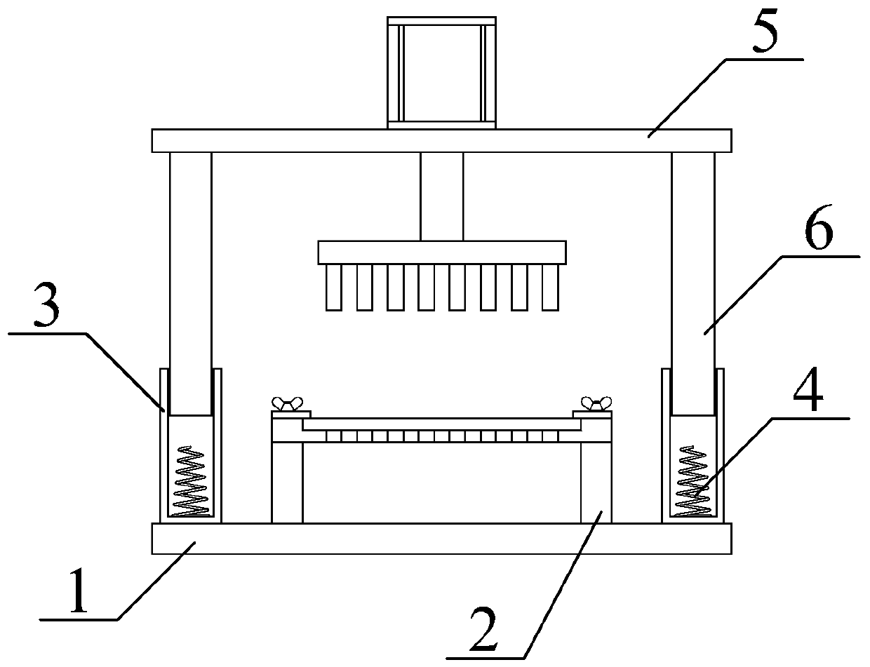
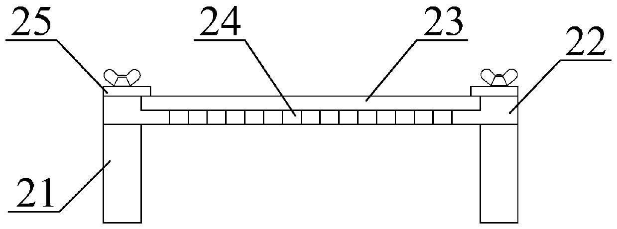
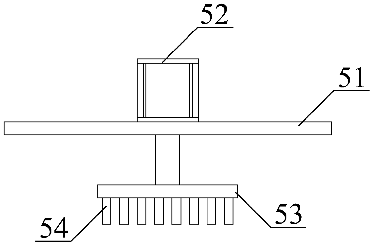
[0021] see Figure 1-3 , the present invention provides a technical solution: a metal stamping equipment, such as figure 1 As shown, it includes a base plate 1, a lower mold assembly 2, a guide sleeve 3, a spring 4, an upper mold assembly 5 and a guide column 6, and four guide sleeves 3 are used, and the guide sleeve 3 is fixed on the base plate 1 by bolts. four corners of the top; the spring 4 adopts four, and the spring 4 is fixed below the inside of the gu...


PUM


Abstract

The invention discloses metal stamping equipment. The metal stamping equipment comprises a bottom plate, a lower die assembly, guide sleeves, spring, an upper die assembly and guide columns; by arranging the lower die assembly, a lower die plate is supported by supporting columns; stamping products generated in the stamping process fall between the supporting columns from a lower die opening, thestamping products can be collected conveniently, centralized processing of the stamping products is facilitated, and the stamping efficiency of the stamping equipment is improved; by arranging the upper die assembly and the lower die assembly, stamping is conducted by adopting a plurality of stamping rods and the lower die opening, multiple stamping products can be obtained at a time, the stampingefficiency is high, the stamping quality is consistent, mass production of the stamping products is facilitated, and the use ratio of metal sheets is increased; and by arranging the guide sleeves, the guide columns move in the guide sleeves, thus, the guiding and positioning effects on the upper die assembly are achieved, the interiors of the guide sleeves and the guide columns are all cylindrical, up-down moving of the guide columns is more stable, and the operation stability of the upper die assembly is improved.

Description

technical field [0001] The invention relates to the technical field of metal stamping, in particular to metal stamping equipment. Background technique [0002] Metal gaskets are refined from high-precision, high-hardness sheet materials. They are usually used in the adjustment and measurement of precision molds or precision hardware, or as spacers, and become precision gaskets, sometimes called mold gaskets or precision gaskets. Gap sheets and metal gaskets are generally stamped by a stamping machine. The metal sheet is sent to the bottom of the stamping machine and pressed under the action of a mold. The existing metal stamping equipment is not convenient for collecting stamped products, which is not conducive to stamping The centralized processing of products affects the stamping efficiency of stamping equipment. Therefore, it is urgent to develop a metal stamping equipment to solve the above problems and facilitate market promotion and application. [0003] To this end, ...

Claims


Application Information

Patent Timeline
Patent Type & Authority Applications(China)
IPC IPC(8): B21D22/02B21D37/10B21D37/12B21D43/00B21D43/22B21D55/00
CPCB21D22/02B21D37/10B21D37/12B21D43/003B21D43/22B21D55/00
Inventor 严白双
Owner 严白双
Why Eureka
Try Eureka