Transportation device for production of oil pipe joint of automobile

A technology of oil pipe joints and transportation devices, which is applied in the direction of transportation and packaging, trolleys, motor vehicles, etc., which can solve the problems of being easily affected by inertia, heavy weight of joints, and high density of oil pipe joints, so as to avoid violent impact, facilitate operation, and facilitate Remove the effect

Inactive Publication Date: 2019-11-12
十堰凯鑫汽车零部件股份有限公司
View PDF0 Cites 1 Cited by
  • Summary
  • Abstract
  • Description
  • Claims
  • Application Information

AI Technical Summary

Problems solved by technology

[0003] In the production process of automobile oil pipe joints, it is necessary to use the transportation device to transfer the oil pipe joints. The density of the oil pipe joints is high, and the weight of the joints per unit volume is relatively large. As a result, the existing transportation devices are easily affected by the inertia Therefore, it is urgent to design a transportation device for the production of automobile oil pipe joints to solve the above problems

Method used


Image

  • Transportation device for production of oil pipe joint of automobile
  • Transportation device for production of oil pipe joint of automobile
  • Transportation device for production of oil pipe joint of automobile

Examples


Embodiment 1

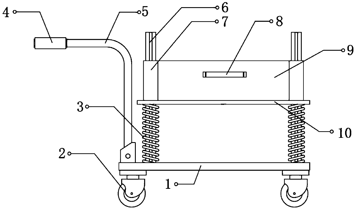
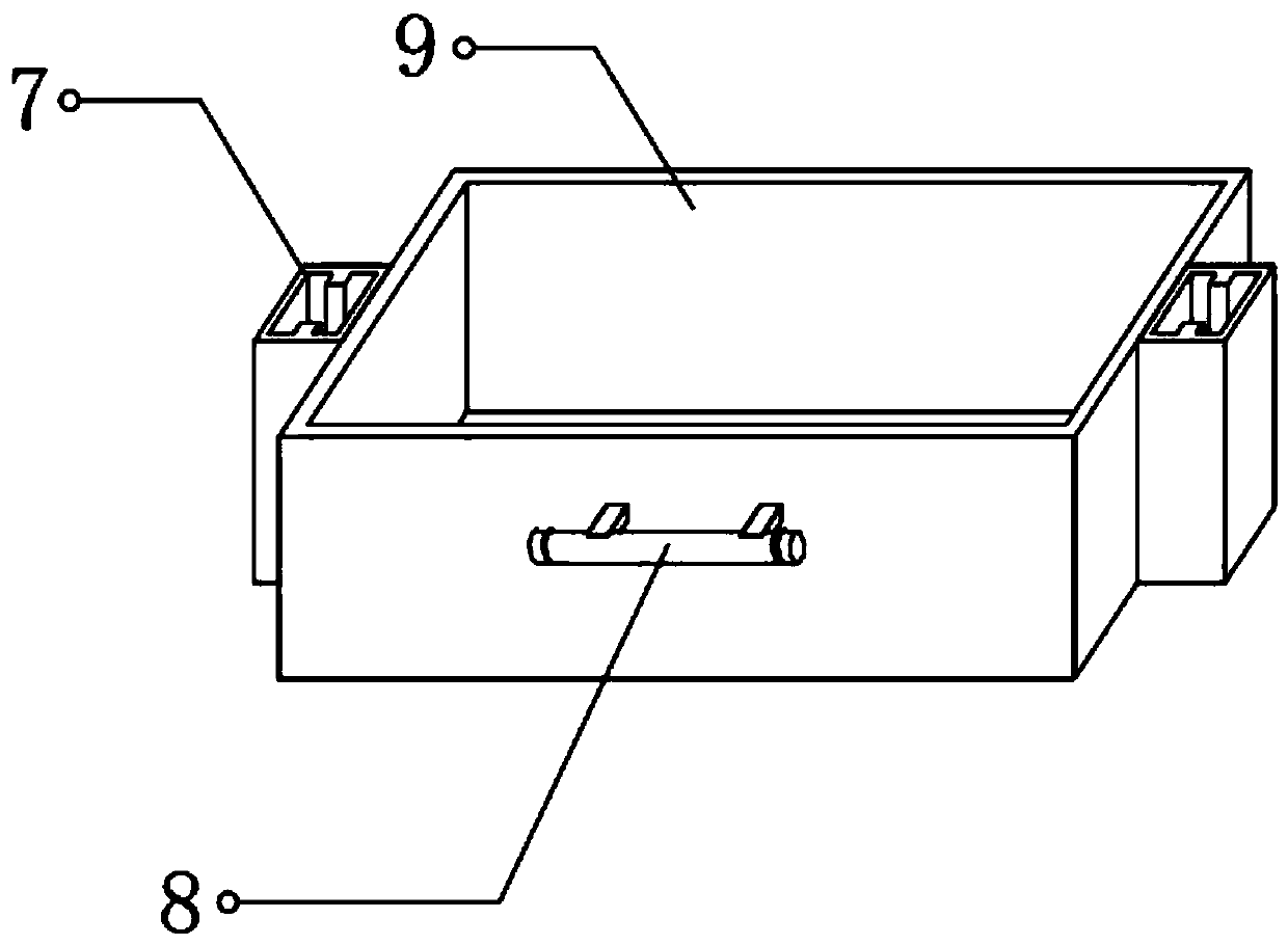
[0026] refer to Figure 1-2 , a transportation device for the production of automobile oil pipe joints, including a chassis 1, universal wheels 2 and push rods 5, four universal wheels 2 are fixedly connected to the four corners of the bottom of the chassis 1, and two push rods 5 are installed in parallel by bolts On one side of the top of the chassis 1, two slide rails 6 are fixedly connected to the top of the chassis 1, and the two slide rails 6 are plugged with the same sliding plate 10, and the two slide rails 6 are slidably connected to the same transport box 9, and The transport box 9 is located on the top of the sliding plate 10, and the oil pipe joint is placed in the transport box 9. The position of the transport box 9 is limited by the slide rail 6 to prevent the transport box 9 from falling under the action of inertia during transportation. At the same time, the slide rail 6 A plurality of transport boxes 9 can be plugged, so that the transport boxes 9 can be stacke...

Embodiment 2

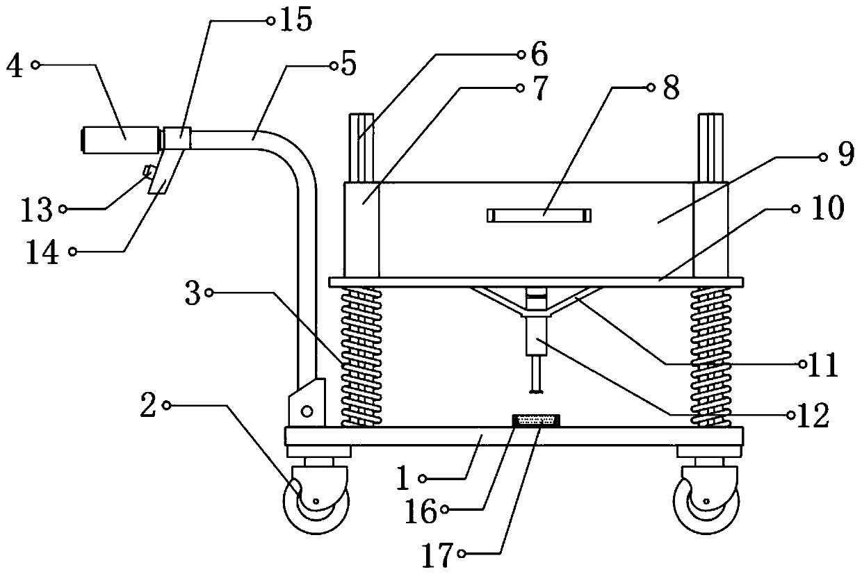
[0032] refer to image 3 , a transportation device for the production of automobile oil pipe joints. Compared with Embodiment 1, the middle position of the bottom of the sliding plate 10 is connected with an electric push rod 12 by bolts, and the outer wall of the middle part of the electric push rod 12 is fixedly connected with a support frame. 11. The top of the support frame 11 is welded to the bottom of the sliding plate 10 .

[0033] Wherein, a card slot 16 is welded at the middle position of the top of the chassis 1, and a rubber pad 17 is clipped inside the card slot 16, and the rubber pad 17 is located directly below the electric push rod 12. When a plurality of transport boxes are inserted on the slide rail 6 At 9 o'clock, the spring 3 is compressed by gravity, and the bottom of the electric push rod 12 is pressed on the top of the rubber pad 17, and the rubber pad 17 buffers the pressure.

[0034] Wherein, one end of two push rods 5 is all sleeved with handle 4, and...


PUM


Abstract

The invention discloses a transportation device for production of an oil pipe joint of an automobile. The device comprises a chassis, universal wheels and push rods, the four universal wheels are fixedly connected to the four corners of the bottom of the chassis, and the two push rods are parallelly installed at one side of the top of the chassis through bolts; two slide rails are fixedly connected to the top of the chassis, the same slide plate is inserted in the two slide rails, the same transportation box is slidingly connected to the two slide rails and located at the top of the slide plate, and two sleeves are welded to the middles of the outer walls of the two sides of the transportation box and sleeve the middles of the slide rails respectively. According to the transportation device, the oil pipe joint can be contained in the transportation box, the transportation box is inserted in the slide rails through the sleeves and limited through the slide rails, and the situation is avoided that the transportation box slides down under the inertia effect in the transportation process. Meanwhile, multiple transportation boxes can be inserted into the slide rails, so that the transportation boxes are stably laminated.

Description

technical field [0001] The invention relates to the technical field of auto parts production, in particular to a transportation device for the production of auto oil pipe joints. Background technique [0002] At present, there are basically three types of oil pipes in automobiles. The gasoline pipe is connected to the gasoline pump and the engine nozzle to provide fuel. There is also a power oil pipe, which provides power oil for the steering gear. The brake oil pipe is connected to the brake pump and the top column of the brake pad. When we step on the brake, the brake pump will press the brake pad through the brake oil pipe. The automobile oil pipe joint is the part that connects the oil pipe. [0003] In the production process of automobile oil pipe joints, it is necessary to use the transportation device to transfer the oil pipe joints. The density of the oil pipe joints is high, and the weight of the joints per unit volume is relatively large. As a result, the existin...

Claims


Application Information

Patent Timeline
Patent Type & Authority Applications(China)
IPC IPC(8): B62B3/04
CPCB62B3/04B62B2203/70
Inventor 陈廷军袁华乔朱伟
Owner 十堰凯鑫汽车零部件股份有限公司
Why Eureka
Try Eureka