Roller coating machine

A coating machine and roller technology, applied in the direction of coating, the device for coating liquid on the surface, etc., can solve the problems of uneven coating at the head and tail, piles of paint, damage to the coating roller, etc., and achieve good plumpness. , to avoid damage, the effect of smooth paint film

Active Publication Date: 2017-04-19
精一机械(中山)有限公司
View PDF6 Cites 4 Cited by
  • Summary
  • Abstract
  • Description
  • Claims
  • Application Information

AI Technical Summary

Problems solved by technology

When coating the workpiece, the head and tail of the plate-shaped workpiece will have the problem of piled paint, resulting in uneven coating of the head and tail
It has a great influence on the appearance of the workpiece and the next process
Moreover, when the thickness of the workpiece has a large error, because the lifting adjustment of the coating roller is rigidly connected, it will often damage the coating roller

Method used


Image

  • Roller coating machine
  • Roller coating machine
  • Roller coating machine

Examples


Embodiment Construction

[0019] The present invention will be described in further detail below in conjunction with the accompanying drawings.

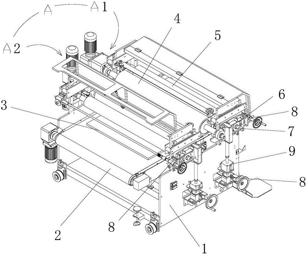
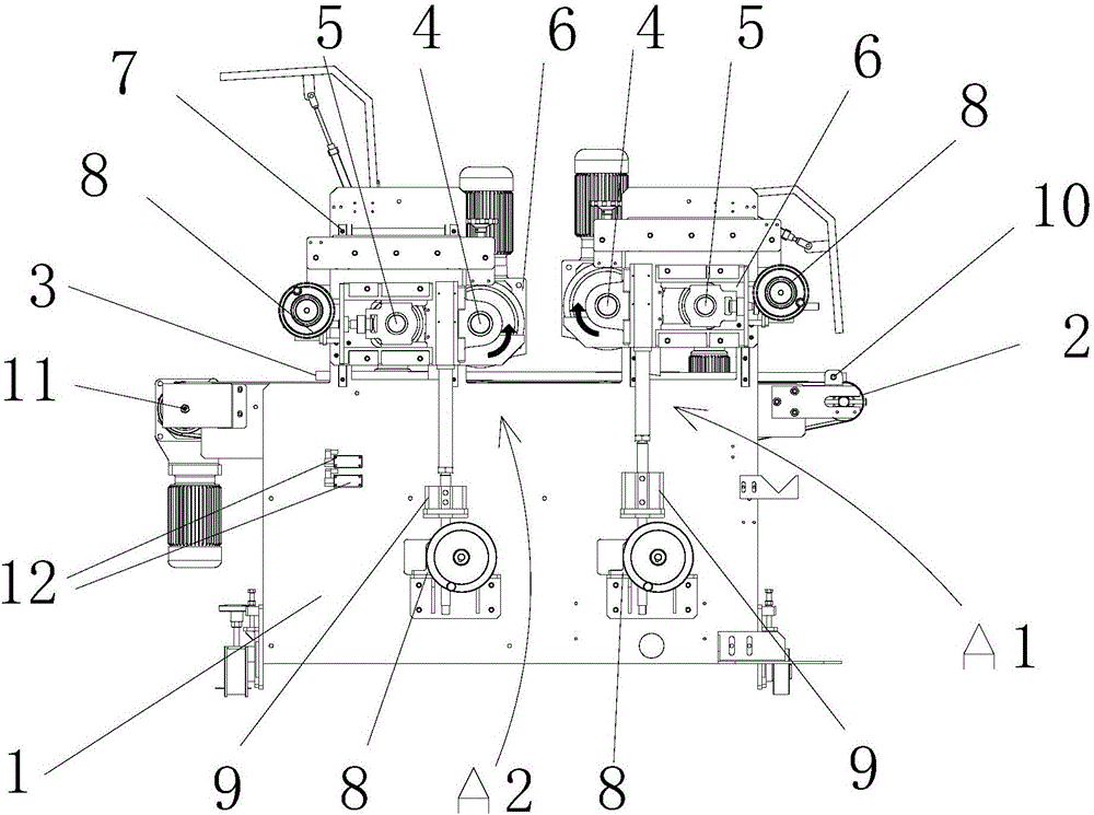
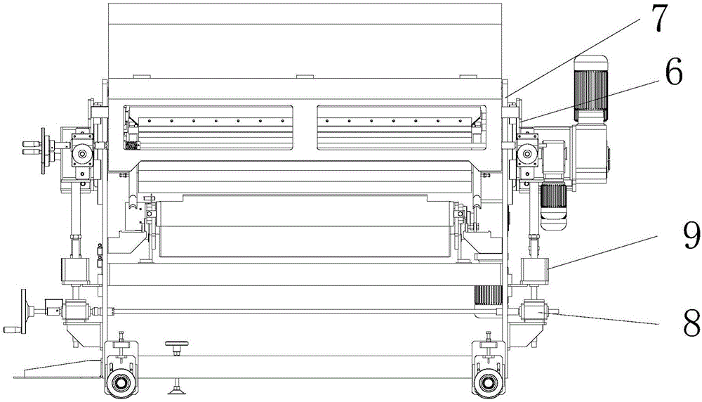
[0020] Figure 1 to Figure 4 A roll coater according to one embodiment of the invention is schematically shown. As shown in the figure, the device includes a machine table 1 , a conveyor 2 and a coating device A arranged above the conveyor 2 .

[0021] In this embodiment, two coating devices A are provided on the machine platform 1, and the two coating devices A are arranged in parallel along the conveying direction of the conveyor. The installation direction of the coating device A is perpendicular to the conveyor 2. Wherein, the running direction of the coating roller 4 of one coating device A1 is the same as that of the conveyor 2 , and the running direction of the coating roller 4 of the other coating device A2 is opposite to that of the conveyor 2 .

[0022] Wherein, the coating device A includes a coating roller 4 , an adjusting roller 5 , an adjusti...


PUM


Abstract

The invention discloses a roller coating machine which comprises a machine table, a conveyor and coating devices. Each coating device comprises a coating roller, an adjusting roller, an adjusting worm gear case and a lifting air cylinder, wherein the coating roller and the adjusting roller are installed on a same sliding block, the sliding block is installed to the machine table through a set of guide rails, the lifting air cylinder is connected with the sliding block and the adjusting worm gear case, and the adjusting worm gear case is installed on the machine table. According to the roller coating machine adopting the technical scheme, it can be ensured that the coating rollers are automatically out of contact from a plate type workpiece under the drive of the lifting air cylinders when the machine halts and the plate type workpiece joint passes, the coating rollers can be protected against damage, and the problem that coating of the head and the tail of the plate type workpiece is irregular can be avoided. A plane film coated through the roller coating machine is smooth, fine, good in plumpness and free of color difference, and no paint piling phenomenon is produced on the front portion and the rear portion of the workpiece. In addition, the lifting air cylinders can achieve the elastic buffer effect, and the coating rollers can be prevented from being damaged when the thickness errors of the plate type workpiece are large.

Description

technical field [0001] The invention relates to printing equipment, in particular to a roller coating machine. Background technique [0002] The full name of the roller coater is a roller coater, which is a device that uses more than one set of rotary rollers to apply a certain amount of coating to a flat material. [0003] Each group of rollers of the roller coating machine is equipped with a lifting adjustment device. The roller coater can adjust the gap and pressure between the rollers, not only the thickness of the coating, so as to obtain the required coating amount. [0004] The coating cylinder of most of existing roller coaters is fixed after adjusting the position. When coating the workpiece, the head and tail of the plate-shaped workpiece will have the problem of piled paint, resulting in uneven coating at the head and tail. It has a great influence on the appearance of the workpiece and the next process. And when the workpiece thickness has a large error, beca...

Claims


Application Information

Patent Timeline
Patent Type & Authority Applications(China)
IPC IPC(8): B05C1/12B05C13/02B05C1/08
CPCB05C1/0821B05C1/0886B05C1/12B05C13/02
Inventor 刘健温亚三冯挺生吴文志刘杰张会雷
Owner 精一机械(中山)有限公司
Why Eureka
Try Eureka