

Light signal to noise ratio monitoring device, signaling device and receiver
一种光信噪比、接收信号的技术,应用在通信领域,能够解决OSNR估计值偏低等问题,达到准确估计、计算过程简单、应用范围广的效果
- Summary
- Abstract
- Description
- Claims
- Application Information
AI Technical Summary
Problems solved by technology
Method used
Image

Examples
Embodiment 1
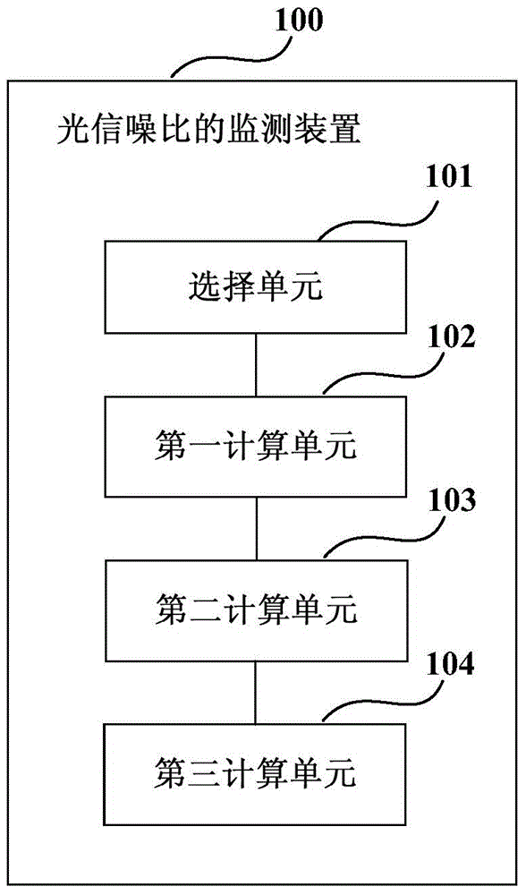
[0031] An embodiment of the present invention provides an optical signal-to-noise ratio monitoring device, and the optical signal-to-noise ratio monitoring device can be used at a receiving end of a communication system. figure 1 It is a schematic composition diagram of the optical signal-to-noise ratio monitoring device of Embodiment 1 of the present invention. Such as figure 1 As shown, the device 100 includes:
[0032] The selection unit 101 is configured to select a phase noise area and / or a polarization crosstalk area in the received signal for calculating noise power based on the positions of the pilot signals in the received signal of the first polarization state and the second polarization state;
[0033] The first calculation unit 102 is configured to calculate the noise power of the received signal of the first polarization state and the second polarization state in the selected phase noise region and / or polarization crosstalk region;
[0034] The second calculatio...
Embodiment 2
[0086] An embodiment of the present invention also provides a signal sending device, which can be used at a transmitting end of a communication system. Image 6 is a schematic diagram of the composition of the signal sending device according to Embodiment 2 of the present invention. Such as Image 6 As shown, the device 600 includes: a sending unit 601, wherein,
[0087] The sending unit 601 is configured to respectively send signals including pilot signals on the first polarization state and the second polarization state, wherein the pilot signals in the signals sent on the first polarization state and the second polarization state have different powers .
[0088] In this embodiment, the method for sending a signal by the sending unit 601 is the same as that described in Embodiment 1. For example, the sending unit 601 may determine the power of the pilot signal in the signal sent on the first polarization state and the second polarization state according to the constellati...
Embodiment 3
[0091] The embodiment of the present invention also provides a receiver, Figure 7 is a schematic diagram of the composition of the receiver of this embodiment. Such as Figure 7 As shown, the receiver 700 includes an OSNR monitoring device 701. The structure and function of the OSNR monitoring device 701 are the same as those described in Embodiment 1, and will not be repeated here.
[0092] Figure 8 It is a schematic block diagram of the system configuration of the receiver according to Embodiment 3 of the present invention. Such as Figure 8 As shown, the receiver 800 includes:
[0093] The function of the front end is to convert the input optical signal into baseband signals in two polarization states. In the embodiment of the present invention, the two polarization states may include H polarization state and V polarization state.
[0094] Such as Figure 8 As shown, the front end includes: local oscillator laser 810, optical mixer (Optical 90deg hybrid) 801, photod...
PUM
 Abstract
Description
Claims
Application Information