
LED mounting substrate, led

A technology for mounting, LED chips, applied in sustainable manufacturing/processing, final product manufacturing, printed circuits, etc., can solve problems such as poor heat dissipation, insufficient heat dissipation function of solder pads, etc. damage, easy to locate

Active Publication Date: 2019-06-04
CCS INC
View PDF3 Cites 0 Cited by
  • Summary
  • Abstract
  • Description
  • Claims
  • Application Information

AI Technical Summary

Problems solved by technology

[0004] However, when the electronic component is an LED, for example, such an anti-displacement structure has the advantage that the optical axes can be aligned with high precision, and on the other hand, it may cause problems in terms of heat dissipation.
That is, in the case of LEDs where heat dissipation is particularly important, if the pad and the terminal bonding surface only partially overlap as described above, there will be a problem that the heat dissipation function of the pad cannot be fully exerted.

Method used


Image

  • LED mounting substrate, led
  • LED mounting substrate, led
  • LED mounting substrate, led

Examples


Embodiment Construction

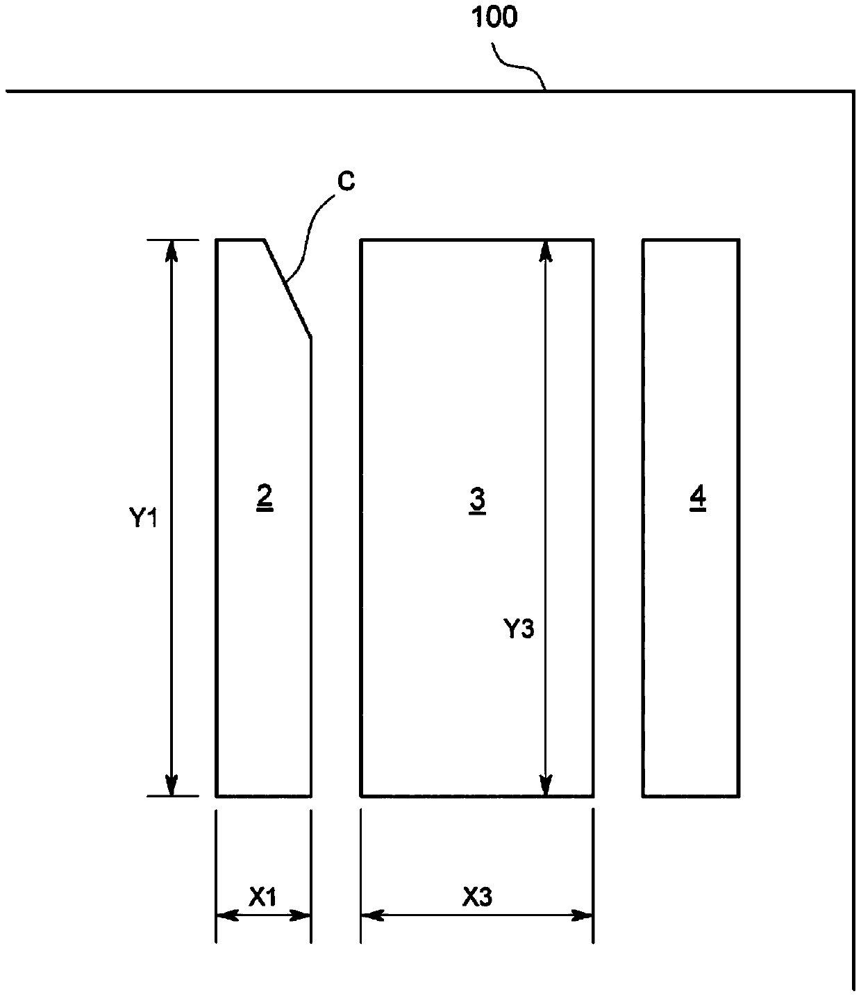
[0041] The LED mounting substrate 100 (hereinafter also referred to as "substrate 100") of the present embodiment is a printed circuit board having pads 2, 3, 4 formed on its surface for soldering. Terminals 13, 14, 15 of a surface mount type LED 1 (hereinafter also referred to as "LED 1").

[0042] Before describing this substrate 100, first, the outline of the LED 1 to be mounted on this substrate 100 will be described.

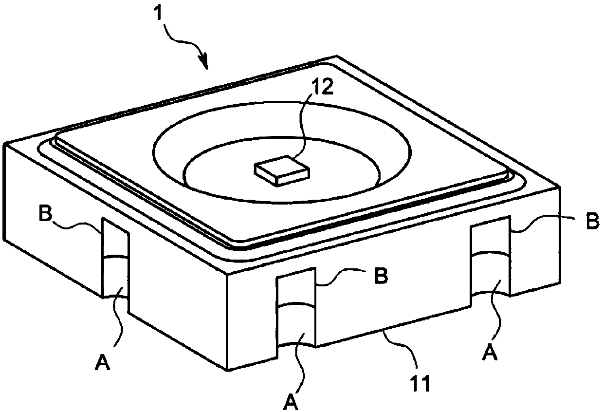
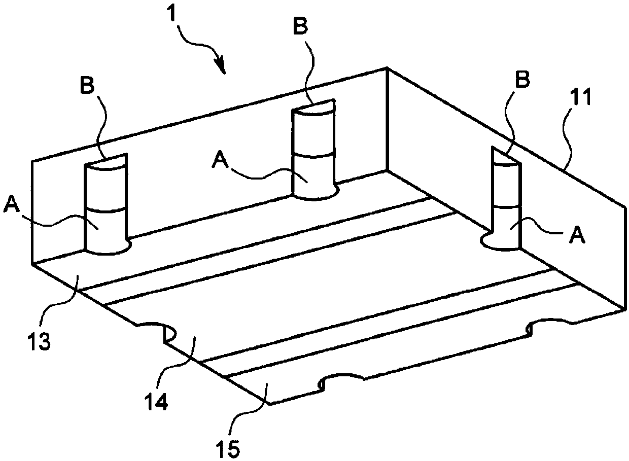
[0043] likefigure 1 , figure 2 As shown, the LED 1 is a surface-mounted LED in a flat rectangular shape (a square shape here), and includes a package body 11, an LED chip 12, and a plurality of (three here) terminals 13, 14, 15. The package body 11 is in the shape of a flat plate square, the LED chip 12 is bonded to the center of a bottomed circular hole opened on the surface side of the package body 11, and the plurality of terminals 13, 14, 15 are formed by gold plating. The back side of the package body 11 .

[0044] The terminals 13 , 14 , and 15 ha...


PUM


Abstract

The present invention is a substrate for LED mounting, the purpose of which is to easily perform positioning during soldering of a surface mount type LED (1) without impairing the heat dissipation function, and it is characterized in that, except for the solder pad with the strongest heat dissipation function ( At least one welding pad (2) other than 3) (hereinafter referred to as "special-shaped welding pad (2)") has a shape different from that of the terminal (13) corresponding to the welding pad, and the LED (1 ) has a non-overlapping part corresponding to the non-overlapping part of the terminal (13) of the special-shaped welding pad (2) and the non-overlapping part of the special-shaped welding pad (2), and the non-overlapping part is set in the following way: only for the LED (1 ) is installed at the regular position, due to the surface tension of the melted solder, the solder pads (2), (3), (4) overlap with the terminals (13), (14), (15) The resultant force of the partial interface forces is balanced.

Description

technical field [0001] The present invention relates to an LED mounting substrate and LED on which a mounting type LED is mounted. Background technique [0002] Surface-mount electronic components are mounted on a substrate by being placed on pads to which solder paste or the like has been previously applied, and soldered by, for example, reflow soldering. In addition, there is usually a slight difference in size between the pad and the terminal joint surface of the electronic part (it is recommended in the design manual that the pad be designed to be larger than the terminal joint surface of the electronic part), and as a result, in the reflow process, the solder When melted, electronic parts can sometimes move on pads causing unforeseen misalignment. Of course, it is also considered that if the shape of the pad is matched with the shape of the terminal joint surface of the electronic component with high precision, such a misalignment will not occur. However, in reality, t...

Claims


Application Information

Patent Timeline
Patent Type & Authority Patents(China)
IPC IPC(8): H01L33/00H01L33/62H01L33/64
CPCH01L33/62H01L33/64H01L33/486H05K1/111H05K3/3431H05K2201/09381H05K2201/10106H05K2201/10969H05K2203/048Y02P70/50
Inventor 八木一乃大
Owner CCS INC
Learn More