Bubble porous body and method for producing the same

A technology of porous bodies and bubbles, applied in the field of porous porous bodies and their manufacture, can solve the problems of lack of heat resistance, deterioration, and release of low molecular siloxane components, and achieve the effect of not impairing heat dissipation

Active Publication Date: 2022-07-08
INOAC TECHN CENT +1
View PDF6 Cites 0 Cited by
  • Summary
  • Abstract
  • Description
  • Claims
  • Application Information

AI Technical Summary

Problems solved by technology

However, in Patent Document 1, there is no description of the above-mentioned problem of shape followability, that is, the viewpoint of flexibility and its solution.
In addition, since this foamable composition contains a polysiloxane-based surfactant as an essential component, when a heat sink manufactured from this composition is exposed to high temperature, there is a problem that the low-molecular-weight siloxane component is released and deteriorates. , lack of heat resistance

Method used


Image

  • Bubble porous body and method for producing the same
  • Bubble porous body and method for producing the same
  • Bubble porous body and method for producing the same

Examples


Embodiment 1 and 2

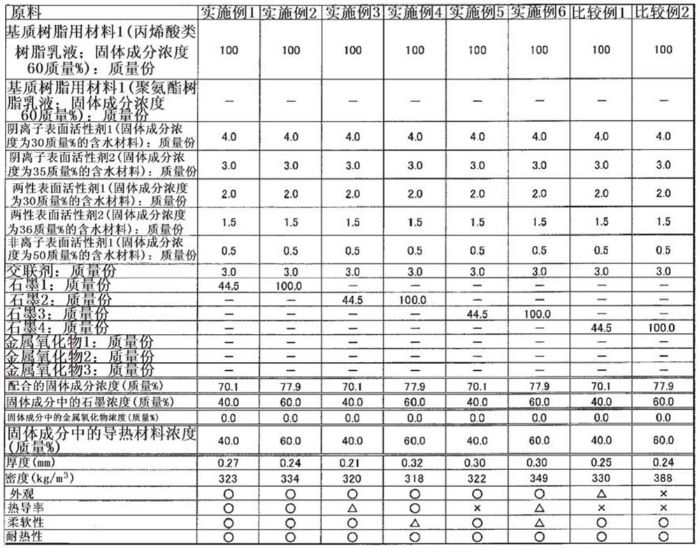
[0109] Graphite 1, Anionic Surfactant 1, Anionic Surfactant 2, Amphoteric Surfactant 1, Amphoteric Surfactant 2, and Nonionic Surfactant 1 were mixed in the proportions shown in the table below, and a cross-linking agent was added thereto, An aqueous dispersion of graphite 1 was prepared, added to 100 parts by mass of the above-mentioned material 1 for matrix resin, and mixed to prepare liquid compositions for Examples 1 and 2, respectively.

[0110] The total solid content concentration of the liquid composition, the solid content concentration of the thermally conductive material, and the like are as described in the following table. The pH of the liquid composition was 8.4. In addition, the viscosity is also the viscosity range in which mechanical foaming is possible.

[0111] Each liquid composition prepared above was foamed by a mechanical foaming method (stirring 500 revolutions, stirring time 3 minutes, temperature 23° C.), and then, the above liquid composition was pl...

Embodiment 3 and 4

[0113] The liquid compositions for Examples 3 and 4 having the compositions shown in the following tables were prepared in the same manner, except that the graphite 2 was used instead of the graphite 1 in the preparation of the above-mentioned liquid compositions. The pH of each liquid composition was 8.4 similarly to the liquid composition of Example 1.

[0114] Except having used the liquid compositions of Examples 3 and 4, respectively, the sheet-like cellular porous bodies of Examples 3 and 4 were produced in the same manner as described above, and evaluated in the same manner. The results are shown in the table below.

Embodiment 5 and 6

[0116] In the preparation of the above-mentioned liquid compositions, except that graphite 3 was used instead of graphite 1, each liquid composition for Examples 5 and 6 having the compositions shown in the following table was prepared in the same manner. The pH and viscosity of each liquid composition were not significantly different from those of the above-mentioned examples, nor were there significant differences regarding bubble formation by the mechanical foaming method.

[0117] Except having used the liquid compositions of Examples 5 and 6, respectively, the sheet-like cellular porous bodies of Examples 5 and 6 were produced in the same manner as above, and evaluated in the same manner. The results are shown in the table below.


PUM

PropertyMeasurementUnit
particle sizeaaaaaaaaaa
glass transition temperatureaaaaaaaaaa
densityaaaaaaaaaa

Abstract

To provide a novel cellular porous body that can be used as a heat dissipating member and a method for producing the same. A cellular porous body comprising a matrix resin and a thermally conductive material dispersed in the matrix resin, and at least spherical graphite as the thermally conductive material; and a method for producing a cellular cellular body, comprising: a foaming step, Mechanical foaming of a liquid composition containing a resin having functional groups in side chains, a foaming agent and spherical graphite; and a curing step, by allowing the functional groups of the above-mentioned resins to react with each other, and / or to make the functional groups of the polyfunctional crosslinking agent. react with each other, and / or react the functional group of the resin with the functional group of the polyfunctional crosslinking agent, thereby curing the liquid composition, wherein the foaming step and the curing step are carried out simultaneously, and / or in the above After the foaming step, the above-mentioned curing step is implemented.

Description

technical field [0001] The present invention relates to a porous porous body useful as a heat-dissipating member for electronic and electrical equipment products (electronic products), particularly thin, high-performance smart phones, personal computers, televisions and other electronic and electrical equipment products with complex internal structures, and a method for producing the same . Background technique [0002] Electronic and electrical equipment products (electronic products), especially products such as smartphones, personal computers, and televisions, are being reduced in thickness and higher in performance every year. On the other hand, due to an increase in data processing speed and the like, the amount of heat generated increases, and the internal structure is complicated, so that heat tends to accumulate. The generated heat may cause problems such as short lifespan of electronic components, deformation of the casing due to thermal expansion, and low-temperat...

Claims


Application Information

Patent Timeline
Patent Type & Authority Patents(China)
IPC IPC(8): C08J9/30C08J3/24C08K3/04C08K7/18C08L101/00
CPCC08J3/24C08J9/30C08K3/04C08K7/18C08L101/00C08J9/0066C08K3/22C08L33/00C08J2205/05C08J2333/00
Inventor 菊地敦纪几井隆介
Owner INOAC TECHN CENT
Why Eureka
Try Eureka