Switching Regulator And Power Supply Device Including The Same
A technology of switching regulators and inductors, which is applied in the direction of circuit devices, circuit heating devices, printed circuit grounding devices, etc., which can solve the problems of high temperature damage of circuit components and reduce the heat dissipation of circuit components, etc.
- Summary
- Abstract
- Description
- Claims
- Application Information
AI Technical Summary
Problems solved by technology
Method used
Image
Examples
Embodiment approach
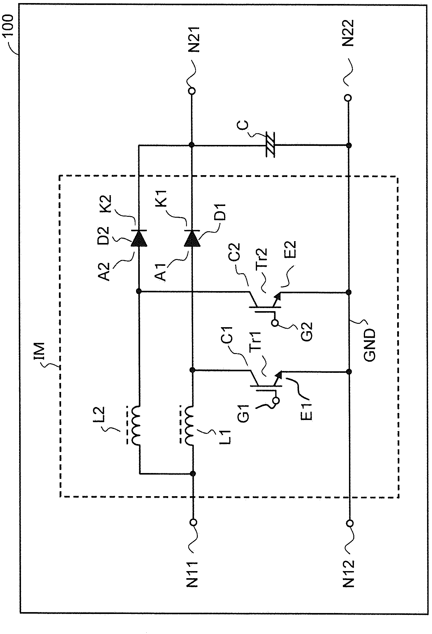
[0030] refer to figure 1 , The circuit configuration of a switching regulator having an interleaved PFC circuit according to this embodiment will be described.
[0031] The power supply device 100 includes the switching regulator according to this embodiment. This switching regulator consists of a converter circuit with an interleaved PFC circuit. An input DC voltage is applied between the input node N11 and the input node N12. The input DC voltage is boosted and smoothed, and output between the output node N21 and the output node N22. The interleaved PFC circuit has an interleaved PFC main circuit IM. The interleaved PFC main circuit IM performs step-up processing on the input DC voltage. The boosted voltage is smoothed by electrolytic capacitor C. The input node N12 and the output node N22 are commonly connected to the ground line GND.
[0032] The interleaved PFC main circuit IM is composed of two sets of main circuit elements. The first group of main circuit compon...
example 2
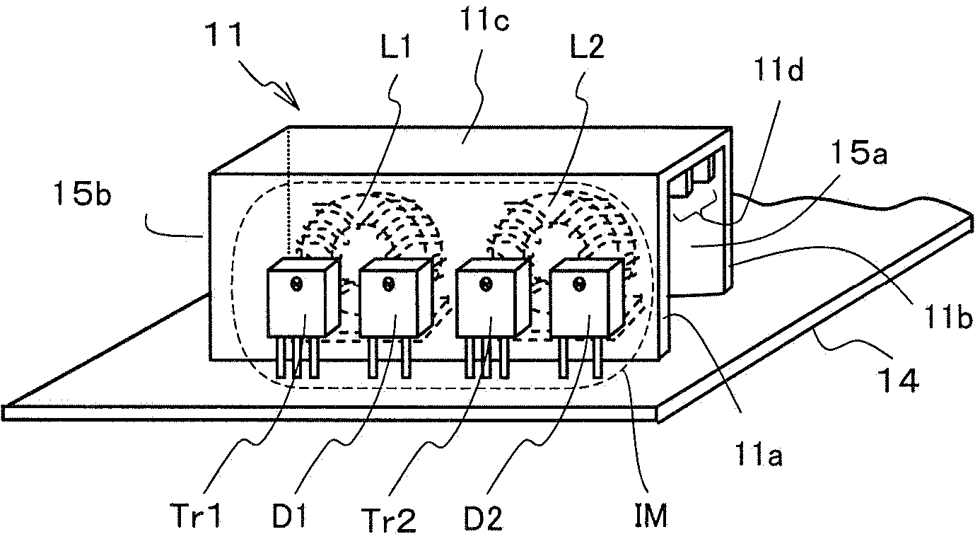
[0051] Refer below Figure 5 , A perspective view of a main circuit element arrangement of a switching regulator having an interleaved PFC circuit according to Modification 2 of the present embodiment will be described.
[0052] A perspective view of a main circuit element arrangement of a switching regulator including an interleaved PFC circuit according to Modification 2 of the present embodiment will be described below.
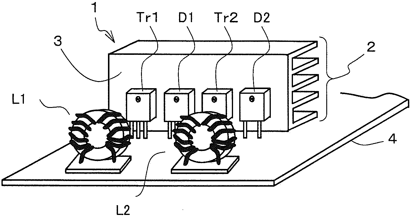
[0053] The configuration of the interleaved PFC circuit according to the second embodiment modification figure 1 The embodiment shown is the same. In addition, in image 3 and Figure 5 The circuit components and heat sinks with the same designation are also the same in structure and will not be described again.
[0054] In Modification 2, a plurality of heat dissipation holes 15 are formed on the third heat dissipation portion 11 c of the heat sink 11 . The opening 15 a and the opening 15 b are provided in the space region of the heat sink 11 where ...
Deformed example 3
[0057] Refer below Figure 6 , A perspective view of a main circuit element arrangement of a switching regulator having an interleaved PFC circuit according to Modification 3 of the present embodiment will be described.
[0058] The configuration and the figure 1 The embodiment shown is the same. In addition, in Figure 6 and image 3 , Figure 4 , Figure 5 The circuit components and heat sinks with the same designation are also the same in structure and will not be described again.
[0059] A switching regulator having an interleaved PFC circuit according to Modification 3 has Figure 4 The ground wire 13 included in Modification 1. and, with Figure 5 In the same manner as Modification 2, a plurality of heat dissipation holes 15 are provided on the third heat dissipation portion 11c of the heat sink 11 . The ground potential is provided through the ground wire 13, which can improve the shielding effect of the radiator 11. Moreover, the heat dissipation holes 15 c...
PUM
 Abstract
Description
Claims
Application Information
 - R&D
- Intellectual Property
- Life Sciences
- Materials
- Tech Scout
- Unparalleled Data Quality
- Higher Quality Content
- 60% Fewer Hallucinations
Browse by: Latest US Patents, China's latest patents, Technical Efficacy Thesaurus, Application Domain, Technology Topic, Popular Technical Reports.
© 2025 PatSnap. All rights reserved.Legal|Privacy policy|Modern Slavery Act Transparency Statement|Sitemap|About US| Contact US: help@patsnap.com


