
Clutch devices for electrical switch operating mechanisms

A clutch device and operating mechanism technology, which is applied in the direction of contact operating mechanism, electric switch, electrical components, etc., can solve the problem of large axial size of the clutch mechanism, and achieve the effect of reducing the overall size and facilitating miniaturized design and manufacture

Active Publication Date: 2016-08-24
XUJI GRP +2
View PDF9 Cites 0 Cited by
  • Summary
  • Abstract
  • Description
  • Claims
  • Application Information

AI Technical Summary

Problems solved by technology

[0005] The invention provides a clutch device for an electric switch operating mechanism to solve the technical problem in the prior art that the clutch body moves axially along the rotating shaft to switch between electric and manual operation, which results in a larger axial size of the clutch mechanism.

Method used


Image

  • Clutch devices for electrical switch operating mechanisms
  • Clutch devices for electrical switch operating mechanisms
  • Clutch devices for electrical switch operating mechanisms

Examples


Embodiment Construction

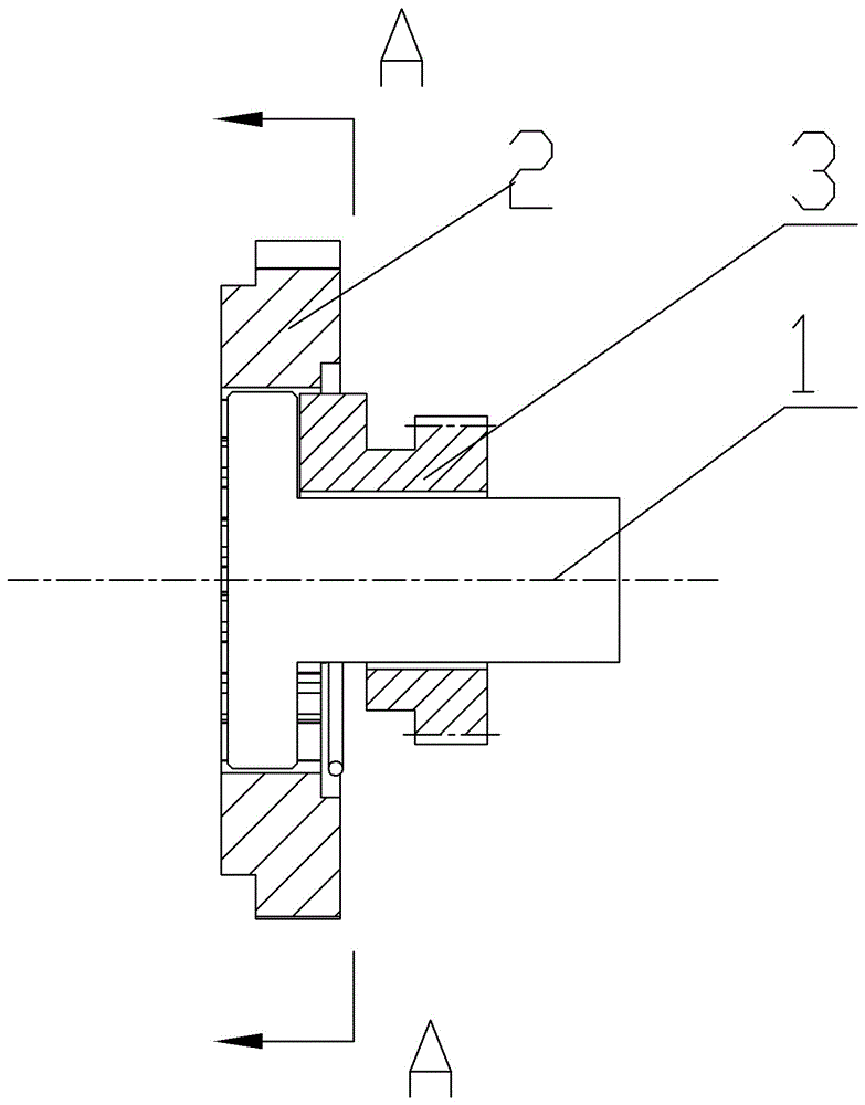
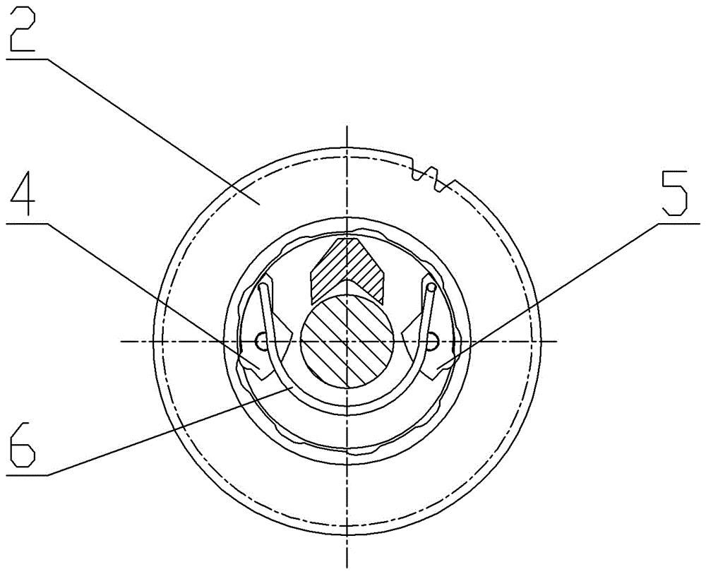
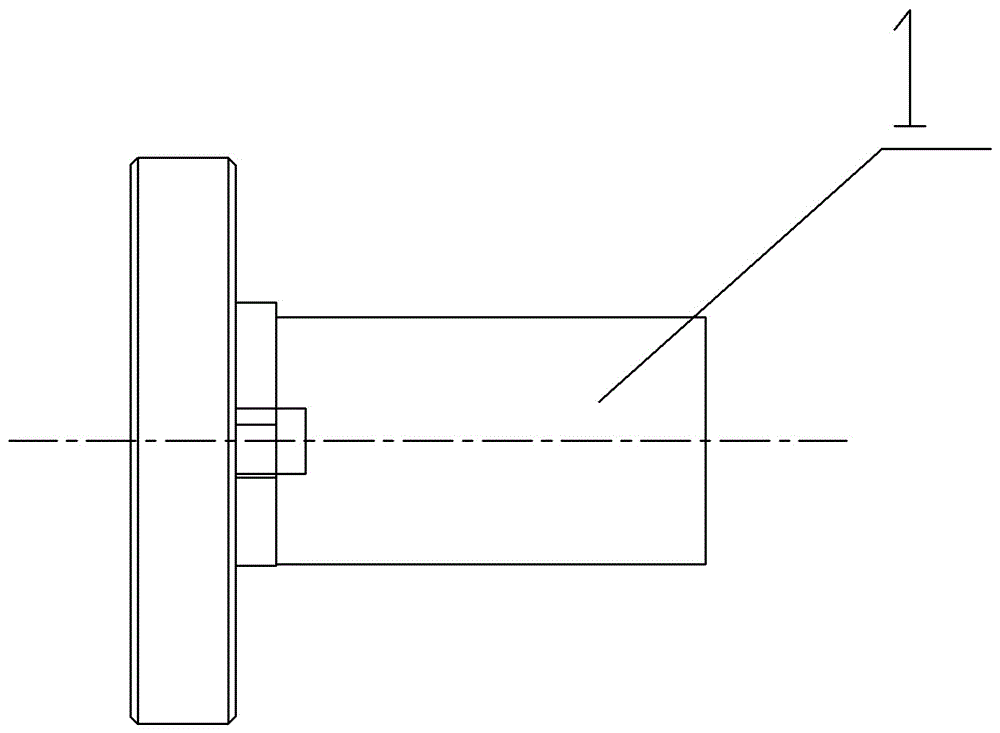
[0030] Such as Figure 1 to Figure 10 As shown, an embodiment of a clutch device for an electric switch operating mechanism. The clutch device in this embodiment includes a rotating main shaft 1 extending axially along the front and rear directions. The driving wheel 3, the electric driving wheel and the manual driving wheel 3 both adopt the ring gear structure, the rotating main shaft 1 here is a stepped shaft with the stepped surface 1-3 facing forward, and the electric driving wheel 2 is set on the large diameter of the stepped shaft section, and on the hole section where the inner hole of the electric driving wheel 2 extends to the small diameter section of the stepped shaft, a transmission card slot 2-1 is arranged, and there are a plurality of transmission card slots 2-1 evenly distributed around the circumference of the electric drive wheel, while the manual The driving wheel 3 is sleeved on the small-diameter section of the stepped shaft, and the rear side of the manua...


PUM


Abstract

The invention provides a clutch device for an electric switch operating mechanism. The clutch device comprises a rotating spindle, a transmission cam structure and an elastic member, an electric driving wheel is mounted on the rotating spindle in a sleeved manner and provided with transmission clamping grooves, the transmission cam structure comprises cam portions assembled on the rotating spindle in a hinged manner, the cam portions are provided with driving protrusions, the elastic member applies an acting force to the cam portions to force the same to rotate so as to enter the corresponding transmission clamping grooves, a manual driving wheel is mounted on the rotating spindle in a sleeved manner, releasing protrusions are arranged on the cam portions, and the transmission cam structure is provided with a jacking-pressing portion used for being in jacking-pressing fit with the manual driving wheel to drive the rotating spindle to rotate by the manual driving wheel through the transmission cam structure. Clutch switching of electric operation and manual operation is realized through the cam portions which rotates around the circumferential direction of cam hinging shafts, the cam portions do not need to slide in the axial direction of the rotating spindle, and outline dimension of the whole clutch device can be reduced effectively.

Description

technical field [0001] The invention relates to a clutch device for an electric switch operating mechanism. Background technique [0002] The circuit breaker switch, isolating switch and grounding switch in the electrical switch are necessary equipment for power transmission and switching. The operating mechanism inside an electrical switch. The operating mechanism is usually driven by the motor installed in the electrical switch. The operating mechanism can usually realize electric operation and manual operation, and the switching between electric operation and manual operation can be realized through the clutch device provided on the high-voltage switch. [0003] An operating mechanism of a high-voltage switch is disclosed in the Chinese utility model patent specification whose authorized announcement number is CN2708481Y. There is a clutch mechanism between them. The clutch mechanism includes a clutch body coaxially set on the rotating main shaft. The clutch body and th...

Claims


Application Information

Patent Timeline
Patent Type & Authority Patents(China)
IPC IPC(8): H01H3/58
CPCH01H3/58
Inventor 吴小钊王廷华赵洪柏郑晓果刘永庆
Owner XUJI GRP
Learn More