Multifunctional electric bed
A multi-functional electric bed and bed frame technology, applied in the direction of hospital beds, medical science, hospital equipment, etc., can solve the problems of increasing the work intensity and burden of medical staff or patients' family members, so as to reduce labor intensity and burden, and facilitate the adjustment of bed angle , the effect of increasing the connection strength
- Summary
- Abstract
- Description
- Claims
- Application Information
AI Technical Summary
Problems solved by technology
Method used
Image
Examples
Embodiment 1
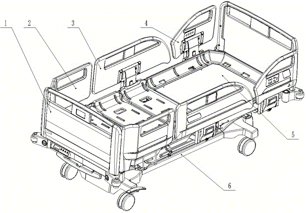
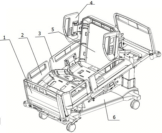
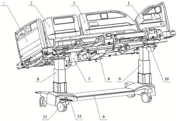
[0040] Example 1, such as Figure 1-19 Shown:
[0041]A kind of multifunctional electric bed, comprises the head of a bed 1 that matches mutually, guardrail, bed panel 5 and chassis 6 with adjustable angle, and described guardrail comprises tail guardrail 2, middle guardrail 3 and head guardrail 4; Said chassis 6 includes a bottom cover 15 and a steel chassis 14, and the front and rear ends of the chassis 6 are symmetrically provided with lifting columns 9, and the lifting columns 9 are provided with a first tilting assembly 7 and a second tilting assembly for adjusting the tilting angle of the upper bed frame 8. Two tilting assemblies 10, the first tilting assembly 7 and the second tilting assembly 10 are respectively provided with a first rotating assembly 28 and a second rotating assembly 39; both ends of the steel chassis 14 are symmetrically provided with column bottoms support 13, casters 11 and brake pedal 12; the installation position of the column base 13 is correspo...
Embodiment 2
[0052] Example 2, such as Figure 4~13 Shown:
[0053] The assembly steps of the underframe 5 are: first assemble the frame of the underframe 6 and the casters 11, then assemble the lifting column 9 and the bottom cover 15, and fix the lifting column 9 with corresponding fasteners.
[0054] The assembly steps of the first tilting assembly 7 are as follows: the first tilting assembly 7 is assembled by the first rotating assembly 28 and the first connecting piece assembly 29, and then the first rotating assembly 28 and the first connecting piece assembly 29 are assembled with a tilting motor connection, the tail of the motor is connected with an adjustable bolt 18 and fixed with a lock nut 35, which can properly adjust the front and rear positions of the motor. This special structure can adjust the leveling purpose of the left and right tilt function of the present invention during installation to offset During electrical leveling, due to the phenomenon that the bed is not hori...
Embodiment 3
[0055] Example 3, such as Figures 14 to 18 Shown:
[0056] The assembly steps of the second tilting assembly 10 are: assembling the second rotating assembly 39 with the second connecting assembly 38, the second rotating assembly 39 can rotate around the central axis of the second connecting assembly 38, and cooperate with the rotation of the first tilting assembly 7, Complete the completion of the left and right tilting function of the upper bed frame 8. Both ends of the second tilting assembly 10 are provided with tilting slideways 44 for installation and connection with the upper bed frame 8 .
[0057] The first tilting assembly 7 and the second tilting assembly 10 are respectively connected on the two lifting columns 9, carefully observe the structural design of the skeleton of the upper bed frame 8, and one end of the upper bed frame 8 skeleton is equipped with a bearing 41, where the bearing 41 is connected to the first The inclined slides 44 of the two inclined assemb...
PUM
 Abstract
Description
Claims
Application Information
 - R&D
- Intellectual Property
- Life Sciences
- Materials
- Tech Scout
- Unparalleled Data Quality
- Higher Quality Content
- 60% Fewer Hallucinations
Browse by: Latest US Patents, China's latest patents, Technical Efficacy Thesaurus, Application Domain, Technology Topic, Popular Technical Reports.
© 2025 PatSnap. All rights reserved.Legal|Privacy policy|Modern Slavery Act Transparency Statement|Sitemap|About US| Contact US: help@patsnap.com


