Bearing outer ring cleaning device

A cleaning device and technology for bearing outer rings, applied in cleaning methods and tools, cleaning methods using tools, chemical instruments and methods, etc., can solve problems such as inability to clean bearings, and achieve reasonable structure and good cleaning effect

Active Publication Date: 2017-04-26
安徽千禧精密轴承制造有限公司
8 Cites 15 Cited by

AI-Extracted Technical Summary

Problems solved by technology

[0004] However, the existing technology can...

Method used

Hairbrush comprises horizontal bar 201 and bristle 202; Horizontal bar 201 is horizontally located at cleaning box 1 inner top, and is positioned at the top of...

Abstract

The invention relates to the field of bearing cleaning devices, in particular a bearing outer ring cleaning device. The bearing outer ring cleaning device comprises a cleaning box and a hairbrush. The hairbrush is horizontally arranged in the upper portion of the cleaning box. The bearing outer ring cleaning device further comprises a rotary shaft, a double-screw bolt, a driving device and a storage rack. The rotary shaft is arranged right below the hairbrush and one end of the rotary shaft is connected to the driving device; the double-screw bolt is fixedly connected to the right end surface of the rotary shaft; the double-screw bolt is further provided with a nut; the driving device is arranged out of the cleaning box; an opening is formed in the right side face of the cleaning box; and the opening and the rotary shaft are located on a same straight line. The bearing outer ring cleaning device provided by the invention is reasonable in structure, and the storage rack can be extracted out to load a to-be-cleaned bearing; and meanwhile, the outer ring can be cleaned better.

Application Domain

Technology Topic

Image

  • Bearing outer ring cleaning device
  • Bearing outer ring cleaning device
  • Bearing outer ring cleaning device

Examples

  • Experimental program(1)

Example Embodiment

[0021] In order to make the objectives, technical solutions, and advantages of the embodiments of the present invention clearer, the technical solutions in the embodiments of the present invention will be described clearly and completely in conjunction with the accompanying drawings in the embodiments of the present invention. Obviously, the described embodiments It is a part of the embodiments of the present invention, not all the embodiments. Based on the embodiments of the present invention, all other embodiments obtained by those of ordinary skill in the art without creative work shall fall within the protection scope of the present invention.
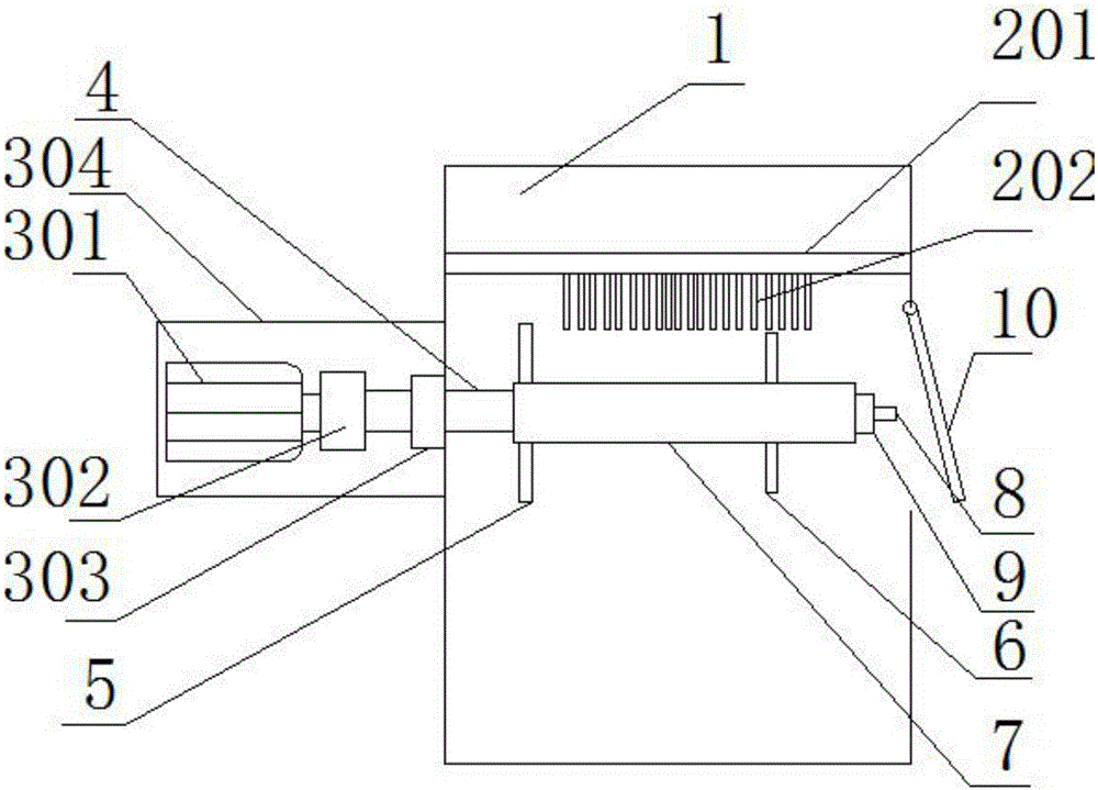
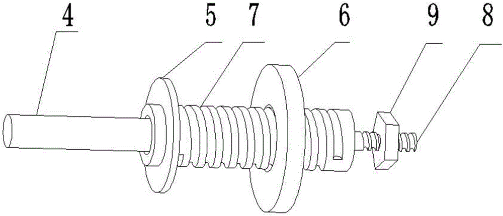
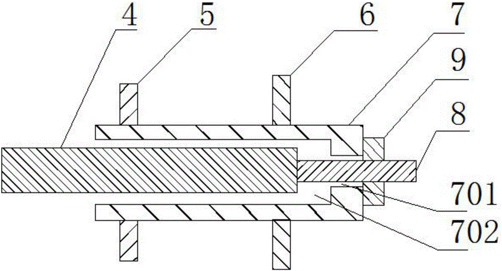
[0022] See Figure 1-3 As shown, the cleaning device for the bearing outer ring according to the embodiment of the present invention includes a cleaning box 1 and a brush. The brush is horizontally arranged in the upper part of the cleaning box 1; it also includes a rotating shaft 4, a stud 8, a driving device, and a load. The rotating shaft 4 is located directly under the brush, and one end is connected with the driving device; the stud 8 is fixedly connected to the right end surface of the rotating shaft 4; the stud 8 is also equipped with a nut 9; the driving device is located outside the cleaning box 1 ; The right side of the cleaning box 1 has an opening; the opening and the shaft 4 are located on the same straight line;
[0023] The carrier includes a sleeve rod 7, a fixed plate 5 and a pressure plate 6. The sleeve rod 7 has a blind hole slot 702 in the middle, and the rotating shaft 4 is arranged in the blind hole groove 702; the sleeve rod 7 is provided with threads on the outer surface; the fixed disc 5 is fixed It is connected to the left end of the sleeve rod 7; the pressure plate 6 has a threaded hole in the middle, and is connected to the sleeve rod 7 through the threaded hole; the right end of the sleeve rod 7 has a through hole 701; the right end of the stud 8 passes through Position through hole 701; nut 9 is threadedly connected to the right end of stud 8.
[0024] The driving device includes a motor room 304, a motor 301 and a coupling 302; the motor 301 room is fixedly connected to the side of the cleaning box 1; the rotating shaft 4 is arranged in the motor room 304; the rotating shaft 4 is connected to the main shaft of the motor 301 through the coupling 302.
[0025] The bristles include horizontal bars 201 and bristles 202; the horizontal bars 201 are horizontally arranged in the upper part of the cleaning box 1 and above the rotating shaft 4; the bristles 202 are arranged side by side under the horizontal bars 201, in order to make the cleaning range more Big.
[0026] A door panel 10 is hinged on the opening to prevent dust from flying out.
[0027] Working principle: First, put multiple bearing outer rings on the sleeve rod 7, then install the pressure plate 6, rotate and tighten the pressure plate 6, so that the pressure plate 6 presses the bearing outer ring; then the sleeve rod 7 is passed through the blind hole slot 702 is installed on the shaft 4, so that the stud 8 passes through the recess hole, and then tightened by the nut 9, so that the sleeve rod 7 is fixed on the shaft 4; then the motor 301 is turned on to rotate the shaft 4, thereby driving the entire series of bearings The outer ring rotates; so that the outer surface of the outer ring and the brush continue to rotate and rub to complete the cleaning work.
[0028] It should be noted that in this article, relational terms such as first and second are only used to distinguish one entity or operation from another entity or operation, and do not necessarily require or imply one of these entities or operations. There is any such actual relationship or order between. Moreover, the terms "include", "include" or any other variants thereof are intended to cover non-exclusive inclusion, so that a process, method, article or device including a series of elements not only includes those elements, but also includes those that are not explicitly listed Other elements of, or also include elements inherent to this process, method, article or equipment. If there are no more restrictions, the element defined by the sentence "including a..." does not exclude the existence of other same elements in the process, method, article, or equipment that includes the element.
[0029] The above embodiments are only used to illustrate the technical solutions of the present invention, not to limit them; although the present invention has been described in detail with reference to the foregoing embodiments, a person of ordinary skill in the art should understand that: The recorded technical solutions are modified, or some of the technical features thereof are equivalently replaced; these modifications or replacements do not cause the essence of the corresponding technical solutions to deviate from the spirit and scope of the technical solutions of the embodiments of the present invention.

PUM

no PUM

Description & Claims & Application Information

We can also present the details of the Description, Claims and Application information to help users get a comprehensive understanding of the technical details of the patent, such as background art, summary of invention, brief description of drawings, description of embodiments, and other original content. On the other hand, users can also determine the specific scope of protection of the technology through the list of claims; as well as understand the changes in the life cycle of the technology with the presentation of the patent timeline. Login to view more.

Similar technology patents

Laser beam coupling output device for high-power semiconductor

InactiveCN102012567AReasonable structureReduce the difficulty of machiningPolarising elementsSemiconductor laser theoryPower semiconductor device
Owner:BEIJING UNIV OF TECH

Classification and recommendation of technical efficacy words

  • Clean well
  • Reasonable structure

Toggle-lever tension lock

Owner:贡特拉姆·克雷泰克

Handheld dust collector

ActiveCN105662272AClean wellGood cleaning effectSuction filtersSuction nozzlesCompanion animalDust collector
Owner:JIANGSU MIDEA CLEANING APPLIANCES

A ceramic insulator device for high voltage capacitor

InactiveCN101546636ALow manufacturing costReasonable structureSuspension/strain insulatorsHigh voltage capacitorsEngineering
Owner:王海龙
Why Eureka
Try Eureka