Automatic cover punching machine and method thereof

A capping machine and automatic technology, applied in metal processing equipment, feeding devices, manufacturing tools, etc., can solve problems such as inaccurate stamping and easy slipping of stamping dies

Active Publication Date: 2017-04-26
FUJIAN YINGHAO CULTURAL & CREATIVE CO LTD
View PDF7 Cites 5 Cited by
  • Summary
  • Abstract
  • Description
  • Claims
  • Application Information

AI Technical Summary

Problems solved by technology

[0003] The present invention improves the above problems, that is, the technical problem to be solved by the present invention is that the existing stamping dies are prone to slip in the case of automatic feeding, resulting in inaccurate stamping

Method used


Image

  • Automatic cover punching machine and method thereof
  • Automatic cover punching machine and method thereof
  • Automatic cover punching machine and method thereof

Examples


Embodiment Construction

[0023] The present invention will be described in further detail below with reference to the accompanying drawings and specific embodiments.

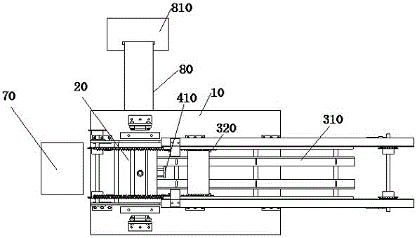
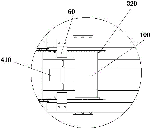
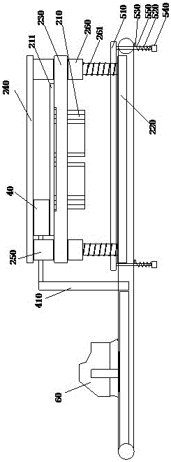
[0024] like Figures 1 to 6 As shown, an automatic capping machine includes a worktable 10 and a transmission mechanism arranged on the worktable 10. The upper front end of the transmission mechanism is provided with a stamping die 20 for capping, and the stamping die includes an upper die 210. and the lower mold 220, the upper mold 210 is fixed on the upper mold base 211 and located above the transmission mechanism, the lower mold 220 is fixed on the worktable 10 and located below the transmission mechanism, and the upper mold base 211 is fixed on the upper mold Panel 230, the upper panel 230 is provided with a pressure plate 240, the pressure plate 240 is fixedly connected to the upper panel 230 through the fixed guide post, and a cylinder 40 is arranged between the pressure plate 240 and the upper panel 230, and the expansion and con...


PUM


Abstract

The invention provides an automatic cover punching machine and a method thereof. The automatic cover punching machine comprises a workbench and a transmission mechanism arranged on the workbench, wherein a punching mold for punching a cover is arranged on the upper part of the front end of the transmission mechanism; the punching mold comprises an upper mold and a lower mold; the upper mold is fixed on an upper mold base and positioned above the transmission mechanism; the lower mold is fixed on the workbench and positioned below the transmission mechanism; the upper mold base is fixed on an upper panel; a pressing plate is arranged on the upper panel; the pressing plate is fixedly connected with the upper panel through a fixed guide column; an air cylinder is arranged between the pressing plate and the upper panel; and the telescopic end of the air cylinder is connected with a top plate arranged longitudinally. The automatic cover punching machine is simple in structure, can guarantee that blanks are fed in place in the transportation process by utilizing the top plate and can guarantee that the blank punching is conducted orderly.

Description

technical field [0001] The invention relates to an automatic capping machine and a method thereof. Background technique [0002] Stamping dies are common tools. However, the existing stamping dies often use automatic conveying devices in the process of transmission. In the process of using automatic conveying devices, only chain shifting is used, which is prone to slippage during the process of blank and chain drive or belt drive. As a result, it is impossible to ensure the accurate position of the blank when it enters the upper surface of the lower die. SUMMARY OF THE INVENTION [0003] The present invention improves the above problems, that is, the technical problem to be solved by the present invention is that the existing stamping die is prone to slip under the condition of automatic feeding, resulting in inaccurate stamping. [0004] The specific embodiment of the present invention is: an automatic capping machine, comprising a worktable and a transmission mechanism ...

Claims


Application Information

Patent Timeline
Patent Type & Authority Applications(China)
IPC IPC(8): B21D22/02B21D43/00B21D43/12B21D45/04
CPCB21D22/02B21D43/003B21D43/12B21D45/04
Inventor 周宗佑
Owner FUJIAN YINGHAO CULTURAL & CREATIVE CO LTD
Why Eureka
Try Eureka