
A static disc precision forming die structure for new energy vehicle air-conditioning compressors

A technology for air-conditioning compressors and new energy vehicles, applied to forging/pressing/hammering machinery, wheels, manufacturing tools, etc., can solve the problem that the height of the end surface of the scroll-shaped protrusion 24 cannot be guaranteed, and it is difficult to ensure the height of the outer ring protrusion 22 Consistent, inconsistent metal flow velocity, etc., to avoid damage to the metal fiber streamline, avoid cracking defects, and improve mechanical properties

Active Publication Date: 2019-04-05
HEFEI UNIV OF TECH
View PDF6 Cites 0 Cited by
  • Summary
  • Abstract
  • Description
  • Claims
  • Application Information

AI Technical Summary

Problems solved by technology

Combined with practical experience, method 1 not only has a low material utilization rate, but also cuts off the fiber streamline of the metal structure during processing, which reduces performance; method 2 is prone to internal defects such as pores; method 3 has inconsistent metal flow rates during conventional extrusion, which is difficult Ensure that the height of the protrusions 22 of the outer ring is consistent, and the height of the end face of the spiral protrusions 24 cannot be guaranteed, and a large amount of machining is still required in the follow-up, which reduces the utilization rate of materials

Method used


Image

  • A static disc precision forming die structure for new energy vehicle air-conditioning compressors
  • A static disc precision forming die structure for new energy vehicle air-conditioning compressors
  • A static disc precision forming die structure for new energy vehicle air-conditioning compressors

Examples


Embodiment Construction

[0021] The embodiments of the present invention are described in detail below. This embodiment is implemented on the premise of the technical solution of the present invention, and detailed implementation methods and specific operating procedures are provided, but the protection scope of the present invention is not limited to the following implementation example.

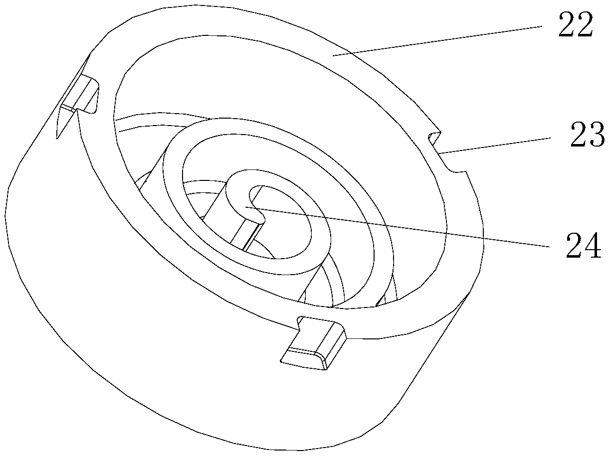
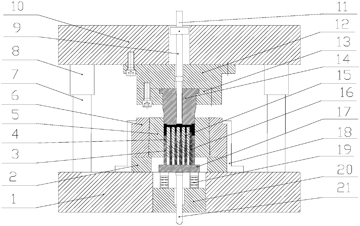
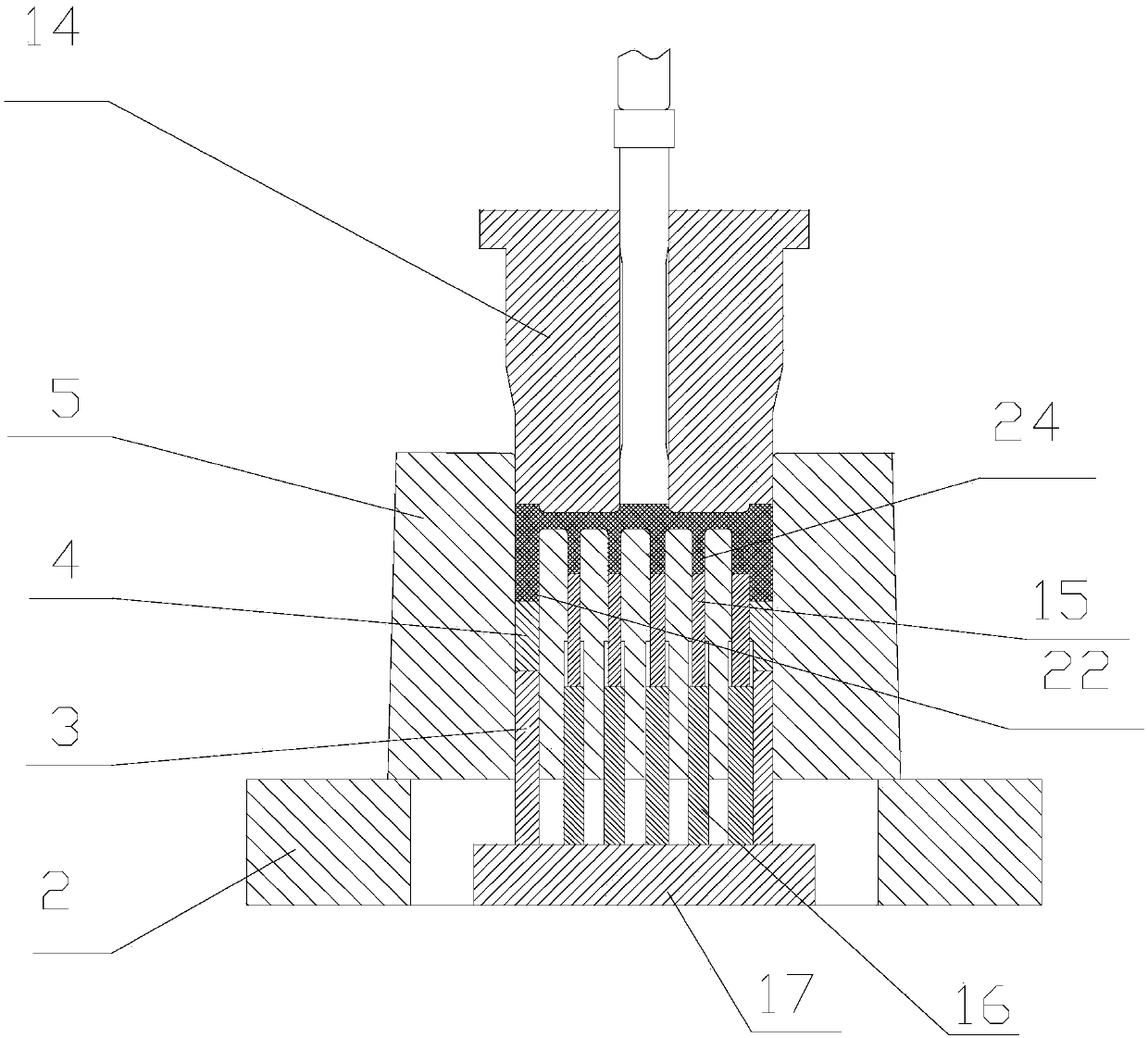
[0022] see Figure 1 to Figure 3 , this embodiment discloses a static disc precision forming mold structure for new energy automobile air-conditioning compressors, the outer ring of the front of the static disc is provided with an annular outer ring protrusion 22, and the middle of the front of the static disc is provided with a scroll-shaped Protrusion 24, the height of the spiral protrusion 24 is lower than the height of the outer ring protrusion 22, the mold structure includes the punch 14 and the die 5, the mold structure also includes a back pressure structure, the back pressure structure includes a scroll bac...


PUM


Abstract

The invention discloses an accurate forming die structure for a stator disc of an air conditioner compressor of a new energy automobile. The die structure comprises a convex die, a concave die and a backpressure structure, wherein the backpressure structure comprises a spiral backpressure body, an outer ring backpressure body, ejection rods, an ejection rod supporting plate, a spring and a cushion plate; the outer ring backpressure body is located at the periphery of the spiral backpressure body; the spiral backpressure body corresponds to a spiral bulge of the stator disc; the outer ring backpressure body corresponds to an outer ring bulge of the stator disc; the ejection rods are arranged at the lower ends of the spiral backpressure body and the outer ring backpressure body; the ejection rod supporting plate is arranged at the lower ends of the ejection rods; the cushion plate is located below the ejection rod supporting plate; the spring is arranged between the ejection rod supporting plate and the cushion plate; and the ejection rod supporting plate in the backpressure mechanism is located below the concave die. Compared with the prior art, the die structure disclosed by the invention has the following advantages: accurate forming for the stator disc can be realized, destroy for a metal fibre flow line due to the subsequent machining is avoided, the utilization rate of materials and the mechanical property of the stator disc are increased, and the cost is reduced.

Description

technical field [0001] The invention relates to a molding die for new energy automobile parts, in particular to a static disk precision forming mold structure for an air conditioner compressor of a new energy automobile. Background technique [0002] The static disk is a key part of the air conditioner of new energy vehicles. As the world's largest new energy vehicle market, according to the "13th Five-Year Plan", the new energy vehicle market will further expand in the future, and the demand for static disks will also continue to increase. At the same time, the static disk, as a key part of the automobile air-conditioning compressor, needs to meet the long-term and stable work, so the requirements for the performance of the static disk are getting higher and higher. Since there are many types of scroll disks, there are many types of static disks, and the structure is complex. For general static disk structures, please refer to figure 1 , the height of the outer ring protru...

Claims


Application Information

Patent Timeline
Patent Type & Authority Patents(China)
IPC IPC(8): B21J13/02B21J13/14B21K1/32
CPCB21J13/02B21J13/14B21K1/32
Inventor 薛克敏谢瑞李萍汪长开孙建辉杜飞
Owner HEFEI UNIV OF TECH
Learn More