Automobile steering sensor installation structure

A steering sensor and installation structure technology, which is applied to steering mechanism, steering control mounted on a vehicle, steering column and other directions, can solve the problems of high development cost and difficult layout of steering sensor installation structure, and achieves large layout space and increased difficulty. and cost, the effect of flexible layout

Active Publication Date: 2017-04-26
CHANGHUI AUTOMOBILE STEERING SYST HUANGSHAN
View PDF5 Cites 2 Cited by
  • Summary
  • Abstract
  • Description
  • Claims
  • Application Information

AI Technical Summary

Problems solved by technology

[0005] The purpose of the present invention is to provide an automobile steering sensor installation structure, which solves

Method used


Image

  • Automobile steering sensor installation structure
  • Automobile steering sensor installation structure
  • Automobile steering sensor installation structure

Examples


Embodiment 1

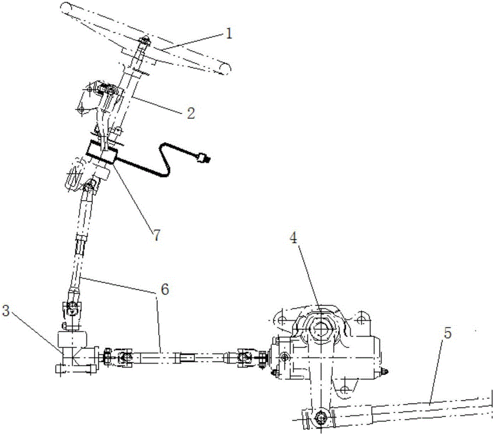
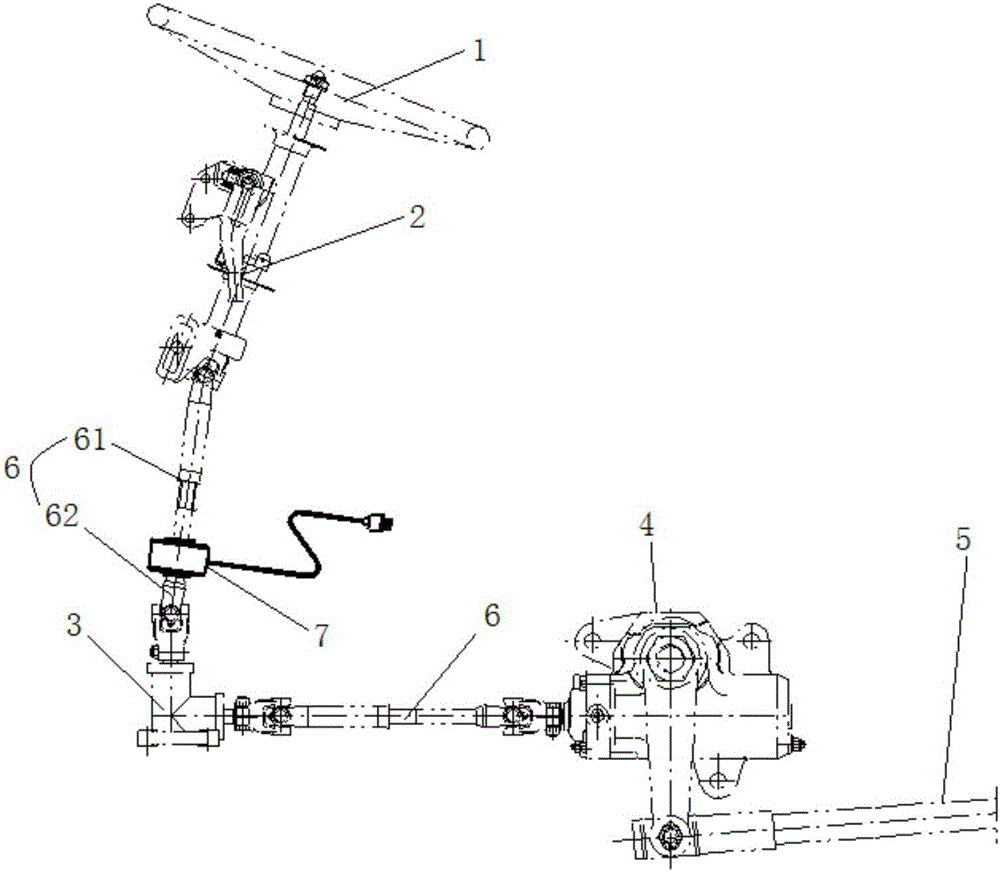
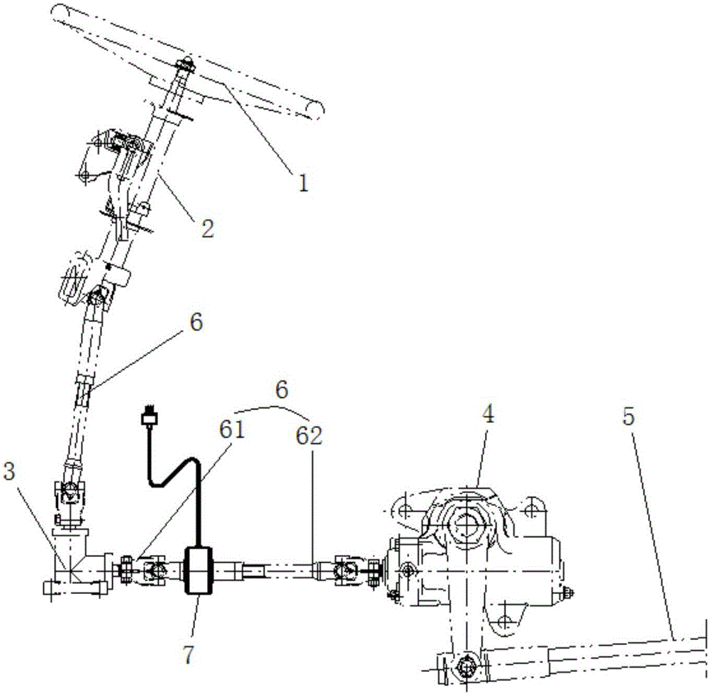
[0023] An automobile steering sensor mounting structure, such as Figures 2 to 5 As shown, it includes a steering wheel 1, a steering transmission device 2 connected to the steering wheel 1, a fixed reversing component 3, a steering gear 4, and a steering rod 5. The steering transmission device 2 and the fixed reversing part 3, and between the fixed reversing part 3 and the steering gear 4 are all connected by a steering transmission shaft 6; the steering transmission shaft 6 is a two-stage structure, including the upper shaft of the steering transmission shaft 61 and steering drive shaft lower shaft 62. A steering sensor 7 is connected between the steering transmission shaft upper shaft 61 and the steering transmission shaft lower shaft 62. The steering sensor 7 is provided with a housing 8 for fixing the steering sensor 7. The steering sensor 7 is provided with a sensor torsion bar. 9. One end of the sensor torsion bar 9 is connected to the upper shaft 61 of the steering tr...

Embodiment 2

[0026] An automobile steering sensor mounting structure, such as Figures 2 to 4 and Figure 6 , Figure 7 As shown, it includes a steering wheel 1, a steering transmission device 2 connected to the steering wheel 1, a fixed reversing component 3, a steering gear 4, and a steering rod 5. Both the steering transmission device 2 and the fixed reversing component 3 , and between the fixed reversing component 3 and the steering gear 4 are connected through a steering transmission shaft 6 . The swing rod 10 is pin-connected with the adjustment rod 12, and an elastic swing hinge mechanism 14 is arranged between the swing rod holder 11 and the adjustment rod 12, and the elastic swing hinge mechanism 14 includes a fixed connection with the swing rod holder 11 The shaft sleeve 141 is provided with an elastic rubber sleeve 142 inside the shaft sleeve 141, and one end of the adjusting rod 12 passes through the elastic rubber sleeve 142 and is fixed. The adjustment rod 12 swings and co...


PUM


Abstract

The invention discloses an automobile steering sensor installation structure which comprises a steering transmission shaft, a steering sensor and a shell used for fixing the steering sensor. A sensor torsion bar is arranged in the steering sensor. The steering transmission shaft comprises an upper steering transmission shaft body and a lower steering transmission shaft body. One end of the sensor torsion rod is connected with the upper steering transmission shaft body, and the other end of the sensor torsion rod is connected with the lower steering transmission shaft body. The shell is fixedly connected with a swing rod. The automobile steering sensor installation structure is further provided with a swing rod fixing base which is fixed to an automobile body. The swing rod fixing base and the swing rod are not located in the same plane. An adjusting rod is arranged between the swing rod fixing base and the swing rod. The adjusting rod is movably connected with the swing rod fixing base and the swing rod. The automobile steering sensor installation structure has the advantages of being convenient to adjust, short in development period and low in cost, and the automobile steering sensor installation structure can be widely applied to the field of automobile steering systems.

Description

technical field [0001] The invention relates to the field of automobile steering systems, in particular to an installation, fixing method and structure of an automobile steering sensor. Background technique [0002] The development of automotive electronic technology is rapid, and the application of new electronic technology has greatly improved the safety and comfort of vehicles. In the electronic control device of automobile steering, information such as steering force, steering wheel rotation speed, and real-time position when steering wheel is turned must be obtained by installing a steering sensor in the steering control mechanism of the vehicle. The automobile steering system is mainly composed of a steering wheel 1, a steering transmission device 2 connected to the steering wheel 1, a fixed reversing component 3, a steering gear 4, and a steering rod 5. The steering transmission device 2 and the fixed reversing component 3, and between the fixed reversing component 3...

Claims


Application Information

Patent Timeline
IPC IPC(8): B62D1/20B62D15/02
CPCB62D1/20B62D15/0225
Inventor 王进丁王正成江新良胡立靖
Owner CHANGHUI AUTOMOBILE STEERING SYST HUANGSHAN
Why Eureka
Try Eureka