Low-power lifting stand column

A low-power, column technology, applied in the direction of lifting devices, etc., can solve the problems of large volume and high power consumption, and achieve the effect of reducing the overall volume, simple structure, and power reduction.

Active Publication Date: 2017-04-26
SHENYANG SIASUN ROBOT & AUTOMATION +1
View PDF5 Cites 3 Cited by
  • Summary
  • Abstract
  • Description
  • Claims
  • Application Information

AI Technical Summary

Problems solved by technology

[0003] In the prior art, all the force for lifting the manipulator comes from the motor, resulting in excessive power consumption and bulky volume

Method used


Image

  • Low-power lifting stand column

Examples


Embodiment Construction

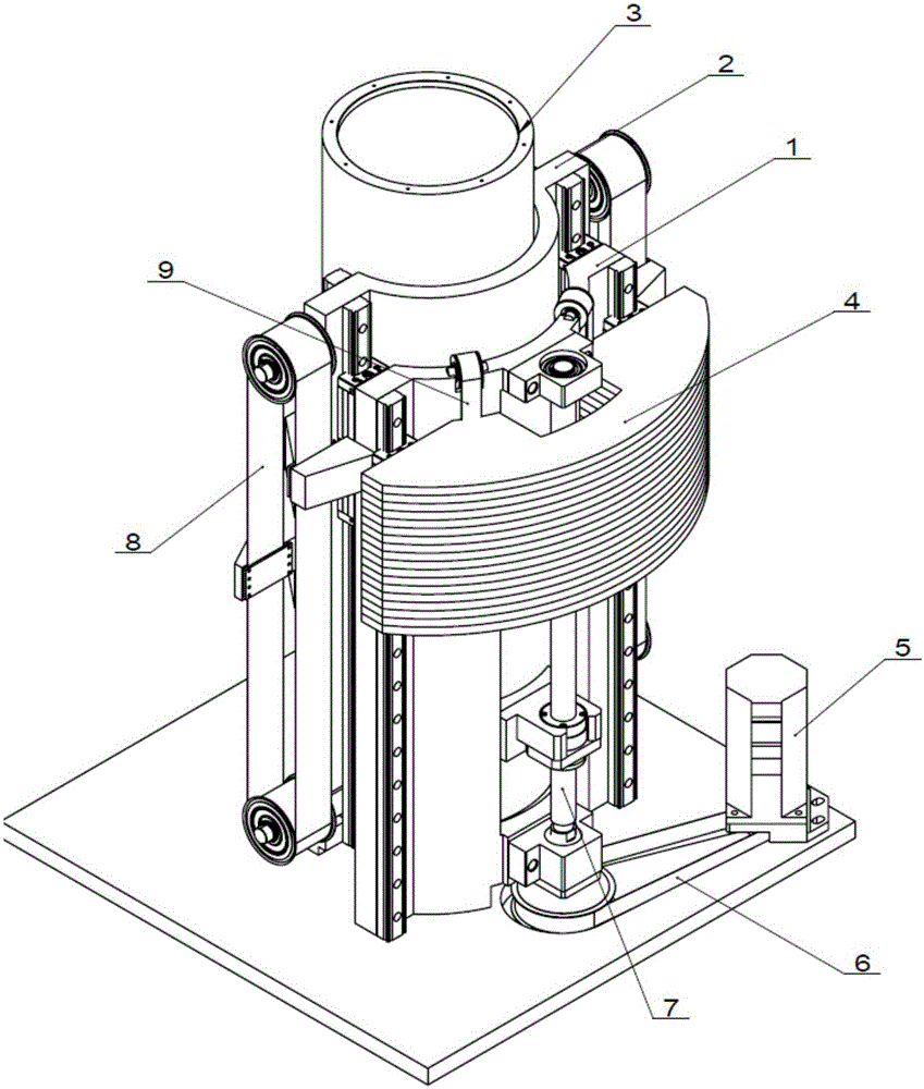
[0017] The specific embodiment of the present invention will be further described below in conjunction with accompanying drawing:

[0018] Such as figure 1 As shown, a low-power lifting column includes a first-level fixed column 1; a second-level lifting column 2; a third-level lifting column 3; a balance counterweight 4; a motor 5; a transmission timing belt 6; a ball screw 7 Lifting synchronous belt 8; counterweight synchronous belt 9, the first-level fixed column is fixed on the base plate, which acts as a fixed support; the second-level lifting column 2 is connected with the first-level fixed column 1 through a linear guide rail, and can be used in The first-level fixed column 1 realizes sliding in the vertical direction; the third-level lifting column 3 is connected with the second-level lifting column 2 through a linear slide rail, and can realize vertical sliding on the second-level lifting column 2. The weight 4 is connected to the first-level fixed column 1 through a...


PUM


Abstract

The invention relates to a mechanical arm lifting column, in particular to a low-power lifting stand column. The low-power lifting stand column comprises a first-stage fixed stand column body, a second-stage lifting stand column body, a third-stage lifting stand column body, balance weights, a motor, a transmission synchronous belt, a ball screw, a lifting synchronous belt and a balance weight synchronous belt. The second-stage lifting stand column body is connected with the first-stage fixed stand column body through a linear guide rail. The third-stage lifting stand column body is connected with the second-stage lifting stand column body through a linear guide rail. The balance weights are connected with the first-stage fixed stand column body through a linear guide rail. The motor is connected with the second-stage lifting stand column body through the transmission synchronous belt and the ball screw and drives the second-stage lifting stand column body to achieve movement in the vertical direction. A nut of the ball screw is fixed to the second-stage lifting stand column body. Due to the fact that the balance weights are additionally arranged, power needed for the lifting stand column can be balanced through the balance weights, the motor power only needs to balance friction resistance and partial gravity in the movement process, the power of the lifting motor is reduced, and the aims of saving energy and reducing the overall size are achieved.

Description

technical field [0001] The invention relates to a manipulator lifting column, in particular to a low-power lifting column. Background technique [0002] In the prior art, a motor is used to provide power, and the lifting of the column is realized through a synchronous belt and a ball screw drive. In the secondary lifting, the lifting distance of the ball screw is enlarged through a fixed synchronous belt. [0003] In the prior art, all the force for lifting the manipulator comes from the motor, resulting in excessive power consumption and bulky volume. Contents of the invention [0004] Aiming at the deficiencies of the prior art, the present invention provides a lifting column that reduces power consumption of a motor through counterweights. [0005] Technical scheme of the present invention is: [0006] A low-power lifting column, including a first-level fixed column, a second-level lifting column, a third-level lifting column, a balance counterweight, a motor, a trans...

Claims


Application Information

Patent Timeline
Patent Type & Authority Applications(China)
IPC IPC(8): B66F3/44
Inventor 曲道奎李学威徐方吴青海何伟全付杰
Owner SHENYANG SIASUN ROBOT & AUTOMATION
Why Eureka
Try Eureka