Wastewater concentrating system and method utilizing flue gas waste heat and based on liquid column evaporation

A waste water concentration and flue gas waste heat technology, which is applied in the field of energy and environment, can solve the problems of wall area ash, nozzles are easy to block, etc., and achieve the effect of reducing desulfurization water replenishment, reducing desulfurization tower pressure, and reducing treatment capacity

Pending Publication Date: 2017-04-26
SHANDONG SHENHUA SHANDA ENERGY ENVIRONMENTAL +1
View PDF4 Cites 10 Cited by
  • Summary
  • Abstract
  • Description
  • Claims
  • Application Information

AI Technical Summary

Problems solved by technology

[0006] The first purpose of the present invention is to provide a waste water concentration system based on liquid column evaporation using the waste heat of flue gas. The system adopts the method of liquid column evaporation by setting up an evaporation tower, and there is no problem such as scaling of the heat exchange surface. Pretreatment overcomes the problems of easy blockage of the nozzle and dust on the wall during spray evaporation

Method used


Image

  • Wastewater concentrating system and method utilizing flue gas waste heat and based on liquid column evaporation
  • Wastewater concentrating system and method utilizing flue gas waste heat and based on liquid column evaporation

Examples


Embodiment 1

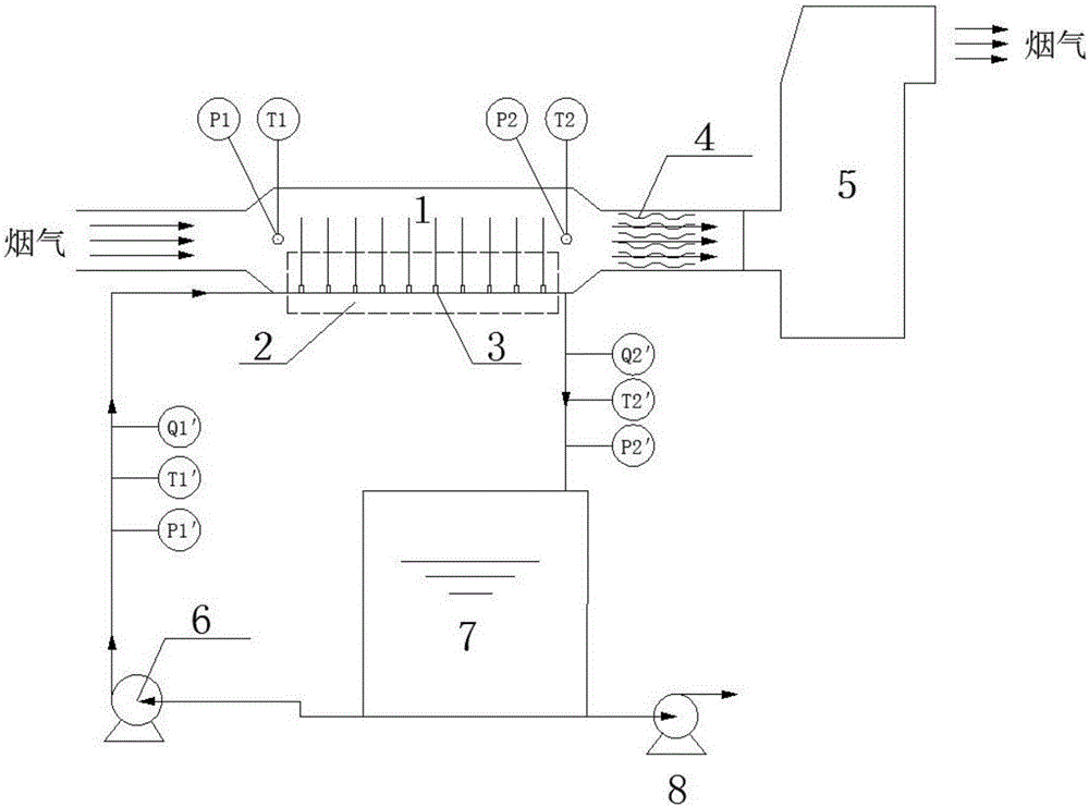
[0050] Take the concentrated circulating water of 300MW unit as an example. Standard flue gas flow is about 1000000Nm 3 Coal-fired power plants with a flow rate of 100t / h and a total salt content of 3000mg / L, the circulating water drainage is pumped into the spray area of ​​the evaporation tower through the wastewater circulation pump, and sprayed into the evaporation tower through the nozzle hole to directly contact with the flue gas for heat transfer After concentration, the waste water is discharged into the waste water storage pool through the outlet of the lower part of the evaporation tower, and is further circulated and evaporated and concentrated by the waste water circulation pump. After being concentrated to a total salt content of 60000mg / L and a waste water flow rate of 5t / h, it is discharged through the waste water discharge pump. Proceed to the next step.

Embodiment 2

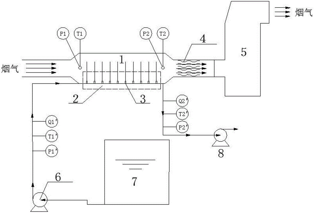
[0052] Take the concentrated desulfurization wastewater of a 300MW unit as an example. Standard flue gas flow is about 1000000Nm 3 / h, the desulfurization wastewater of coal-fired power plants with a flow rate of 10t / h and a total salt content of 30000mg / L is pumped into the spray area of ​​the evaporation tower through the wastewater circulation pump, and sprayed into the evaporation tower through the nozzle hole to directly contact with the flue gas for heat transfer Quality, the total salt content of the concentrated wastewater is 150,000mg / L, and the flow rate is 2t / h. It is directly discharged through the outlet at the lower part of the evaporation tower for the next step of treatment. The difference from the process flow of Example 1 is that when the required concentration ratio of the wastewater is low, the concentrated wastewater at the outlet of the evaporation tower does not need to enter the wastewater storage tank for circulation and concentration, but is directly ...


PUM


Abstract

The invention discloses a wastewater concentrating system and method utilizing flue gas waste heat and based on liquid column evaporation. The system comprises an evaporation tower and is characterized in that the evaporation tower is arranged on one side of the gas inlet end of a desulfurization tower and communicated with the desulfurization tower; the evaporation tower is provided with a spraying area inside, the spraying area comprises a plurality of vertical liquid column spraying orifices used for spraying wastewater, flue gas enters the evaporation tower through the flue gas inlet of the evaporation tower and transfers heat and mass with the wastewater sprayed by the liquid column spraying orifices vertical to or intersecting with the flue gas, the wastewater evaporates after absorbing heat to generate steam which enters the flue gas, the flue gas flows out through the flue gas outlet of the evaporation tower and enters the desulfurization tower, the liquid column spraying orifices are connected with a wastewater storage tank, the evaporation tower is connected with the wastewater storage tank, and the evaporated wastewater enters the wastewater storage tank so as to achieve wastewater circulating concentration. The wastewater concentrating system has the advantages that flue gas waste heat is utilized on the basis that boiler efficiency loss is avoided, the problem of blocking is avoided, wastewater treatment quantity is lowered greatly, desulfurization water and water replenishing are reduced greatly, energy and water are saved, and huge economic and environmental benefits are produced.

Description

technical field [0001] The invention relates to the fields of energy and environment, in particular to a waste water concentration system and method based on liquid column evaporation using waste heat of flue gas. Background technique [0002] Coal-fired thermal power plants are the largest households of industrial water in my country, and their water consumption and displacement are huge. About 40% of industrial water is used in coal-fired thermal power plants, and the annual discharge of coal-fired thermal power plants accounts for about 10% of the discharge of industrial enterprises in the country. With the increasing shortage of water resources and stricter environmental protection requirements, it is imperative to save water and reduce pollution in coal-fired power plants. The zero discharge of wastewater from coal-fired power plants can minimize the use of water resources, minimize or eliminate the discharge of sewage, and has good environmental and economic benefits. ...

Claims


Application Information

Patent Timeline
Patent Type & Authority Applications(China)
IPC IPC(8): C02F1/16C02F1/04B01D53/14
CPCB01D53/1481C02F1/048C02F1/16B01D2252/103B01D2258/0283
Inventor 吴华马春元陈桂芳杨德萍刘晓沈荣胜洪永强
Owner SHANDONG SHENHUA SHANDA ENERGY ENVIRONMENTAL
Why Eureka
Try Eureka