Assembled precast concrete lintel

A technology of precast concrete and concrete beams, applied in the direction of girders, joists, trusses, etc., can solve the problems of inability to connect into one, wet operation, unstable quality, etc.

Active Publication Date: 2019-04-09
CHONGQING NO 3 CONSTR
View PDF9 Cites 0 Cited by
  • Summary
  • Abstract
  • Description
  • Claims
  • Application Information

AI Technical Summary

Problems solved by technology

Cast-in-place concrete lintels are not conducive to on-site civilized construction due to complex construction procedures, unstable quality, high cost, scattered construction sites, and wet operations. Prefabricated concrete lintels can solve the above problems. For this reason, the existing filling In wall construction, prefabricated concrete lintels are often used instead of cast-in-place concrete lintels
[0003] However, the existing precast concrete lintel is at the 90° adjacent door opening of the same height, because one end of it will be cross-affected (the reserved door and window openings often do not match the beam port joints, so the shortened precast concrete lintel is often used and then refill), making it difficult for the lay-up length of precast concrete lintels to meet the design and specification requirements
Moreover, the existing prefabricated concrete lintels cannot be connected as a whole when they are combined with structural columns and ring beams. Therefore, according to the existing construction technology and design requirements, the above-mentioned parts have to be cast-in-place concrete lintels.
[0004] Therefore, it is urgent to invent a new prefabricated concrete lintel, which can not only overcome the disadvantages of complex process, unstable quality and high cost of cast-in-place concrete lintel, but also make its joints match with door and window openings without being affected by crossing. Integrate with structural columns and ring beams

Method used


Image

  • Assembled precast concrete lintel

Examples


Embodiment Construction

[0016] The present invention will be described in further detail below by means of specific embodiments:

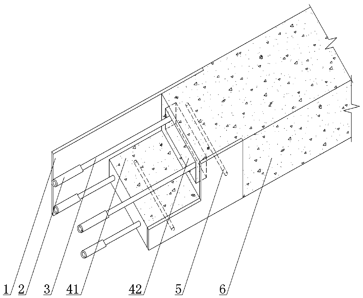
[0017] The reference signs in the drawings of the description include: steel plate 1 , hollow steel pipe 2 , reserved connecting rib 3 , raised portion 41 , recessed cavity 42 , fixed connector 5 , and concrete beam 6 .

[0018] The embodiment is basically as figure 1 Shown: the prefabricated prefabricated concrete lintel includes the prefabricated reinforced concrete beam body, the prefabricated reinforced concrete beam body includes the concrete beam 6 and the steel skeleton, one section of the steel skeleton is arranged inside the concrete beam 6, and the other section is along the length direction of the concrete beam 6 Protrude outside the concrete beam 6 . The combination of the concrete beam 6 and the steel skeleton set inside the concrete beam 6 forms a mid-span prefabricated structure, while the steel skeleton protruding outside the concrete beam 6 belongs to th...


PUM


Abstract

The invention discloses a fabricated type precast concrete lintel which comprises a precast reinforced concrete lintel body. The precast reinforced concrete lintel body comprises a concrete lintel unit and a reinforcement cage. One section of the reinforcement cage is arranged in the concrete lintel unit, and the other section of the reinforcement cage extends out of the concrete lintel unit in the length direction of the concrete lintel unit; and the concrete lintel unit and the section, located in the concrete lintel unit, of the reinforcement cage are combined to form a middle-span precast structure, and the section, extending out of the concrete lintel unit, of the reinforcement cage forms reserved connecting ribs. The lintel has the advantages of traditional precast concrete lintels, overcomes the installation defects of traditional reinforced concrete lintels, and is quite suitable for being popularized in the building industry.

Description

technical field [0001] The invention relates to the technical field of construction, in particular to an assembled prefabricated concrete lintel. Background technique [0002] In the existing filling wall construction, concrete lintels are designed at the openings of doors and windows. According to the existing construction methods, concrete lintels are divided into cast-in-place concrete lintels and prefabricated concrete lintels. Cast-in-place concrete lintels are not conducive to on-site civilized construction due to complex construction procedures, unstable quality, high cost, scattered construction sites, and wet operations. Prefabricated concrete lintels can solve the above problems. For this reason, the existing filling In wall construction, precast concrete lintels are mostly used instead of cast-in-place concrete lintels. [0003] However, the existing precast concrete lintel is at the 90° adjacent door opening of the same height, because one end of it will be cro...

Claims


Application Information

Patent Timeline
Patent Type & Authority Patents(China)
IPC IPC(8): E04C3/20E04C3/293E04C5/18
CPCE04C3/20E04C3/293E04C5/161
Inventor 秦孟良
Owner CHONGQING NO 3 CONSTR
Why Eureka
Try Eureka