Wind energy waterwheel

A technology of waterwheel and wind energy, which is applied in the field of wind energy waterwheel, can solve the problems of less obvious lifting effect, high energy consumption, and high price, and achieve the effect of improving the lifting effect, increasing the service life, and having a compact and reasonable structure

Inactive Publication Date: 2017-04-26
孙亮新
View PDF7 Cites 3 Cited by
  • Summary
  • Abstract
  • Description
  • Claims
  • Application Information

AI Technical Summary

Problems solved by technology

The early waterwheels were all human-pedaled. With the development of science and technology, waterwheels with electricity, diesel, gasoline engines, etc. as power sources replaced human-powered waterwheels, but the price was high and energy consumption was high. Restrictions, pedal type plus sail type directional positioning drive, driving the keel type waterwheel to overturn the water, hindered the popularization and development of water sails, the lifting effect is not obvious, the wooden structure is also easy to damage, and the scope of use is also limited to a certain extent

Method used


Image

  • Wind energy waterwheel
  • Wind energy waterwheel
  • Wind energy waterwheel

Examples


Embodiment 1

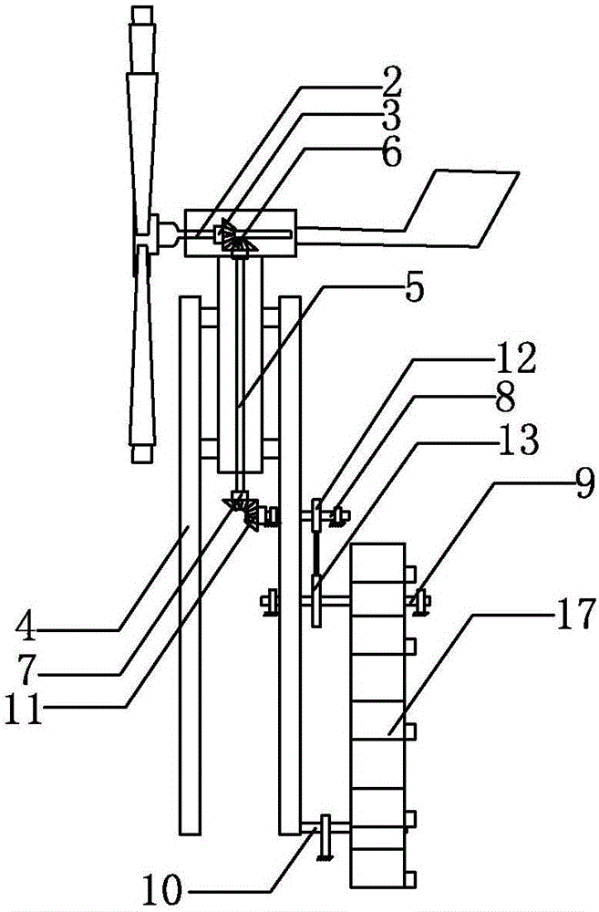
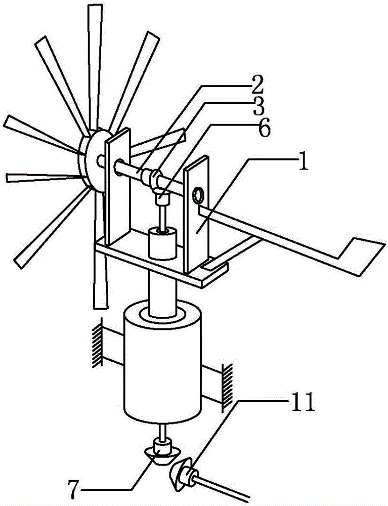
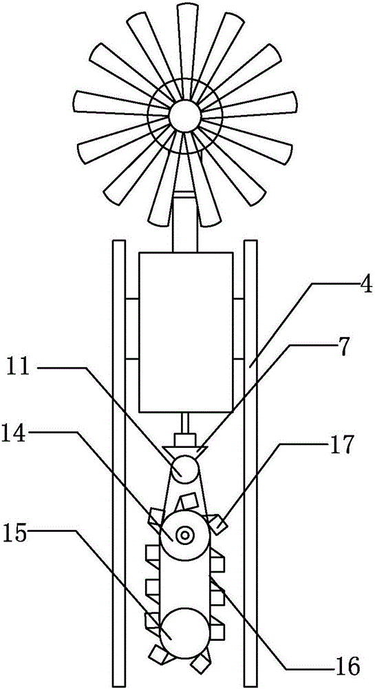
[0031] Such as Figure 1-3 As shown, the wind energy waterwheel includes a wind wing system, a drive system, and a water wheel system. The wind wing system includes a U-shaped bracket 1 and a wind wing shaft 2 that is installed at both ends of the U-shaped bracket 1. The first end of the wind wing shaft 2 rotates Connected to one end of the U-shaped support 1, the second end is set through the other end of the U-shaped support 1, the second end of the wind wing shaft 2 is fixedly provided with a wind wing, and the middle part of the U-shaped support 1 is fixedly provided with a first bevel gear 3; The drive system includes a fixed bracket 4, a drive shaft 5 that is rotatably arranged in the fixed bracket 4, the first end of the drive shaft 5 is fixedly provided with a second bevel gear 6 that meshes with the first bevel gear 3, and the second bevel gear 6 of the drive shaft 5 is The third bevel gear 7 is fixedly arranged at the end; the waterwheel system includes a driven shaf...


PUM


Abstract

The invention discloses a wind energy waterwheel. The wind energy waterwheel comprises a wind wing system, a driving system and a waterwheel system. The wind wing system comprises a U-shaped bracket and wind wing shafts arranged at the two ends of the U-shaped bracket in a penetrating mode, and wind wings are fixedly arranged at the second ends of the wind wing shafts. A first bevel gear is fixedly arranged in the middle of the U-shaped bracket. The driving system comprises a fixing bracket and a driving shaft. A second bevel gear is fixedly arranged at the first end of the driving shaft, and a third bevel gear is fixedly arranged at the second end of the driving shaft. The waterwheel system comprises a driven shaft, a waterwheel driving shaft and a waterwheel bottom shaft. A fourth bevel gear is fixedly arranged at the first end of the driven shaft. A first gear is fixedly arranged in the middle of the driven shaft. A second gear is fixedly arranged on the waterwheel driving shaft. The first gear drives the second gear. A third gear is fixedly arranged on the waterwheel driving shaft. A fourth gear is arranged on the waterwheel bottom shaft. The third gear drives the fourth gear through a first chain. A plurality of water tanks are uniformly arranged on the first chain. According to the wind energy waterwheel, the structure is compact and reasonable, and water supply and irrigation of farmland can be achieved by effectively utilizing wind energy.

Description

technical field [0001] The invention relates to water conservancy equipment, in particular to a wind-powered waterwheel for realizing agricultural water supply, irrigation, power generation and other functions. Background technique [0002] Wind-powered waterwheels, also known as wind-powered waterwheels, have been used by people as early as the Later Han Dynasty. In the Tang Dynasty, it generally appeared beside Haili in various rivers, raising the water below the water level and introducing it into the channel for irrigation of farmland. The early waterwheels were all human-pedaled. With the development of science and technology, waterwheels with electricity, diesel, gasoline engines, etc. as power sources replaced human-powered waterwheels, but the price was high and energy consumption was high. Restrictions, pedal type plus sail type directional positioning drive, driving the keel type waterwheel to overturn the water, hindered the popularization and development of wate...

Claims


Application Information

Patent Timeline
Patent Type & Authority Applications(China)
IPC IPC(8): F03D9/25F03D9/14F03D80/00
CPCY02E10/72Y02E60/16Y02E70/30
Inventor 孙亮新
Owner 孙亮新
Why Eureka
Try Eureka