
A test system for measuring oil film thickness of distribution pair of axial piston pump

An axial piston pump and testing system technology, applied in the field of liquid pumps, can solve the problem of not being able to completely simulate the working conditions of the real pump, restricting the performance and life of the axial piston pump, affecting the performance of the axial piston pump, etc. question

Active Publication Date: 2018-11-16
BEIJING INSTITUTE OF TECHNOLOGYGY
View PDF6 Cites 0 Cited by
  • Summary
  • Abstract
  • Description
  • Claims
  • Application Information

AI Technical Summary

Problems solved by technology

[0002] The axial piston pump is the core component of the hydraulic system, and the distribution pair is the friction pair most likely to fail in the axial piston pump, which seriously restricts the performance and life of the axial piston pump; the condition of the oil film in the gap between the distribution pair determines the The lubrication state of the distribution pair affects the performance of the axial piston pump
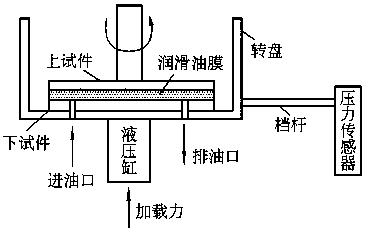
The existing test devices for monitoring the state of the oil film between the friction pairs are mainly divided into two categories. One is to measure the film thickness state directly from the sensor installed in the real pump, but it is difficult to arrange and install the sensor due to the complex structure of the real pump; the other is The single-width distribution pair lubrication characteristic test bench such as figure 1 shown, but the principle of the test bench does not take into account the existence of dynamic pressure support, and cannot completely simulate the working conditions of the real pump

Method used


Image

  • A test system for measuring oil film thickness of distribution pair of axial piston pump
  • A test system for measuring oil film thickness of distribution pair of axial piston pump
  • A test system for measuring oil film thickness of distribution pair of axial piston pump

Examples


Embodiment Construction

[0022] The present invention will be further described in detail below in conjunction with the accompanying drawings and specific embodiments.

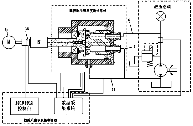
[0023] Such as figure 2 As shown, this technical solution is a subsystem of the axial piston pump distribution pair test bench, and the axial piston pump distribution pair test bench includes the drive motor 15, data acquisition and control assembly, hydraulic assembly, and distribution pair oil film thickness Test system; except for the oil film thickness test system of the distribution sub-assembly, other assemblies are existing technologies. This technical solution only describes the structure and control related to it, and the others will not be described in detail. The data acquisition and control assembly comprises the rotational speed torque sensor 26 installed on the output end of the drive motor 15, the rotational speed torque console for controlling the drive motor 15, the data acquisition module for receiving the rotationa...


PUM


Abstract

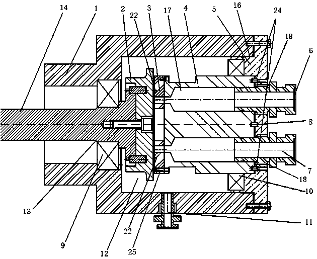
The invention discloses an axial plunger pump flow distribution pair test oil membrane thickness test system and relates to the technical field of an electrically driven liquid pump. The system comprises an experiment compartment, a flow distribution disc, a cylinder flow distribution end surface, a cylinder main body, an end cover, a high-pressure oil pipe, a low-pressure oil pipe, a positioning pin, an A support bearing, a B support bearing and an oil return pipe, wherein the experiment compartment is of a casing-like structure and is internally provided with an experiment oil chamber; in the experiment oil chamber, the flow distribution disc is installed at the right end of a driving shaft; the axle center of the end cover is connected with the axle center of the cylinder main body through the positioning pin; the cylinder main body is internally provided with two plunger chambers symmetrical about the axle center; the end cover is provided with oil pipe holes at positions where the two plunger chambers are in butt-joint cooperation; one of the two oil pipe holes is connected with the low-pressure oil pipe, and the other is connected with the high-pressure oil pipe; and the cylinder flow distribution end surface is circumferentially uniformly provided with probes of three current vortex displacement sensors. A conventional flow distribution pair test simulation apparatus is simplified, and the actual pump working condition of a flow distribution pair is more accurately simulated.

Description

technical field [0001] The invention relates to the technical field of electric-driven liquid pumps, in particular to an experimental device for flow distribution pairs of axial piston pumps. Background technique [0002] The axial piston pump is the core component of the hydraulic system, and the distribution pair is the friction pair most likely to fail in the axial piston pump, which seriously restricts the performance and life of the axial piston pump; the condition of the oil film in the gap between the distribution pair determines the The lubrication status of the distribution pair affects the performance of the axial piston pump. The existing test devices for monitoring the state of the oil film between the friction pairs are mainly divided into two categories. One is to measure the film thickness state directly from the sensor installed in the real pump, but it is difficult to arrange and install the sensor due to the complex structure of the real pump; the other is ...

Claims


Application Information

Patent Timeline
Patent Type & Authority Patents(China)
IPC IPC(8): G01B7/06
CPCG01B7/105
Inventor 周俊杰苑士华胡纪滨荆崇波魏超赵愿
Owner BEIJING INSTITUTE OF TECHNOLOGYGY
Learn More