Check patentability & draft patents in minutes with Patsnap Eureka AI!

Rotary current collector

A technology of rotating conduits and rotating parts, applied in the direction of current collectors, rotary current collectors, circuits, etc., can solve the problems of inconvenience for operators and high installation and maintenance costs.

Inactive Publication Date: 2017-04-26
陈小会
View PDF0 Cites 0 Cited by
  • Summary
  • Abstract
  • Description
  • Claims
  • Application Information

AI Technical Summary

Problems solved by technology

[0002] Some manufacturers used to install trolley line power supply, but the cost of installation and maintenance was very high, and it was extremely inconvenient for operators to go up and down, so they were forced to cancel it.

Method used


Image

  • Rotary current collector
  • Rotary current collector

Examples


Embodiment Construction

[0016] First, connect the electric wire to the incoming line end of the collector and fix it. One end of the distribution box of the tower crane is connected to the outgoing line end of the collector. The pole and the pole of the upper supporting seat are connected in a sliding contact type (to avoid straining the collector during vibration), and the upper seat drives the collector to rotate together under the drive of the slewing mechanism.

[0017] Description of drawings:

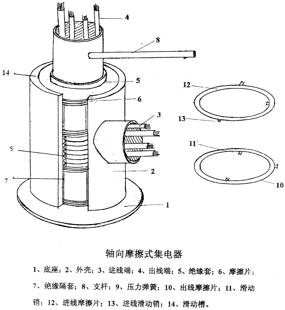
[0018] figure 1 is the diagram of the axial friction collector;

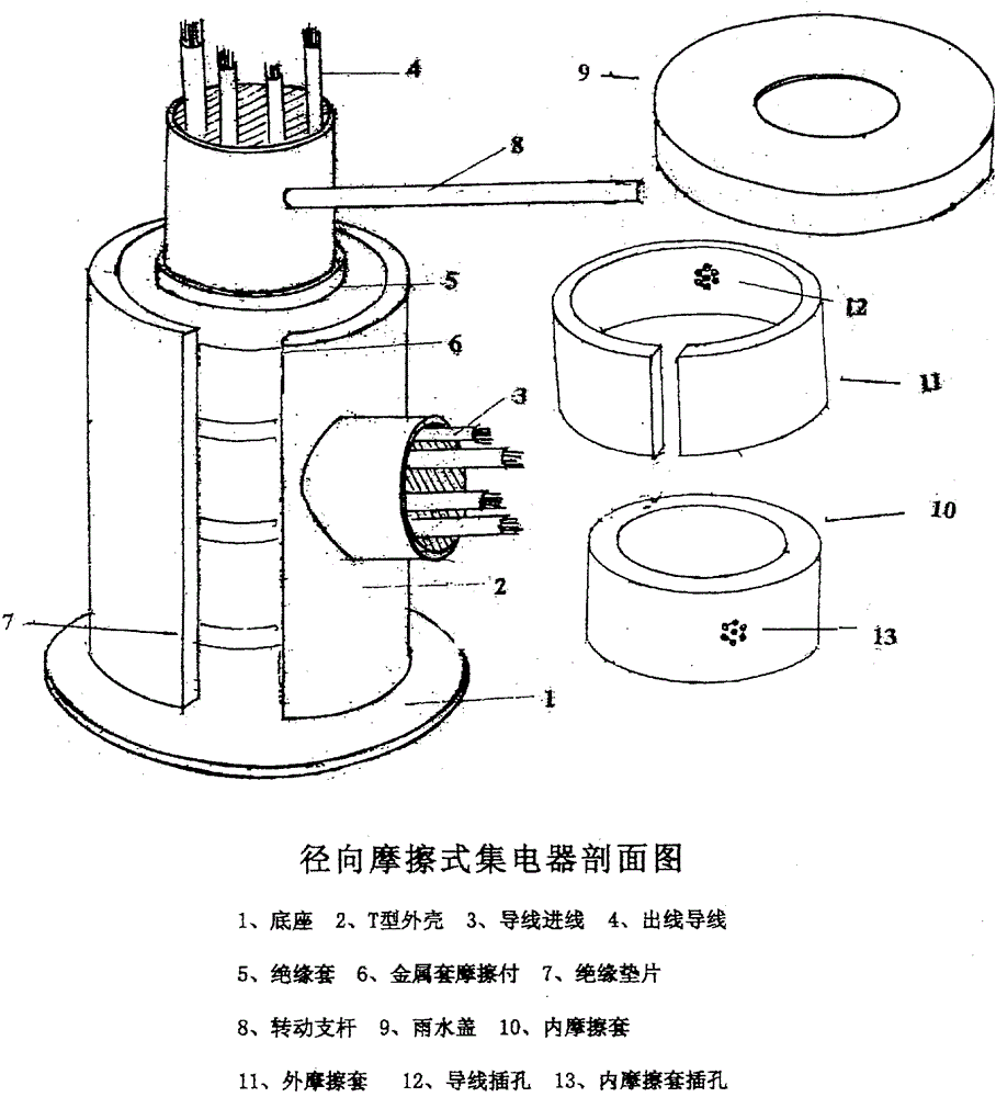
[0019] figure 2 is the diagram of the radial friction collector.


PUM


Abstract

The invention provides a rotary current collector which is divided into a fixed part and a rotary part; the shell is mounted on the cross bar under a rotary bearing through the base and the rotary part is connected with the support rod mounted on the rotary bearing through a support rod. Driven by a rotary mechanism, the support rods rotate together and therefore, prevent the cables from being twisted and damaged. The current collector has a simple structure, is easy to install, has a long service life, and does not need repair. A radial friction-type current collector, after use, realizes the pressure adjustment by the reliance on manual adjustment of the clamp loop and an axial friction type current collector does not require any adjustment; and the damage amount of the friction sheets can be automatically compensated through the elastic force of a pressure spring; and the working principle is similar to a German touch line.

Description

technical field [0001] For a long time, the power supply lines of tower cranes have used the number of turns of the slewing limiter to prevent the cables from being sprained, but in actual operation it has brought a lot of inconvenience and conflicts between operators and workers, so generally new tower cranes are installed on the construction site. were forced to remove the stoppers. It also brings inconvenience to the operator after dismantling. Especially for complex building structures and multi-machine operations, the cables cannot be guaranteed to be twisted. Background technique [0002] Some manufacturers have installed trolley lines for power supply, but the installation and maintenance costs are very high, and it is extremely inconvenient for operators to go up and down, so they were forced to cancel it. [0003] Based on the above situation, current collectors with sliding friction structure are designed, one is radial friction type and the other is axial fricti...

Claims


Application Information

Patent Timeline
Patent Type & Authority Applications(China)
IPC IPC(8): H01R39/64H01R39/02H01R13/52
CPCH01R39/64H01R13/52H01R13/5213H01R39/02
Inventor 陈小会
Owner 陈小会
Features
  • R&D
  • Intellectual Property
  • Life Sciences
  • Materials
  • Tech Scout
  • Unparalleled Data Quality
  • Higher Quality Content
  • 60% Fewer Hallucinations
Learn More