Fixing device for nuclear magnetic resonance examination
A fixed device, nuclear magnetic resonance technology, applied in the field of medical devices, can solve problems such as injury, physical damage, psychological adverse reactions, etc., to achieve the effect of strong practicability, avoidance of sprains, and clear design ideas
- Summary
- Abstract
- Description
- Claims
- Application Information
AI Technical Summary
Problems solved by technology
Method used
Image
Examples
Embodiment 1
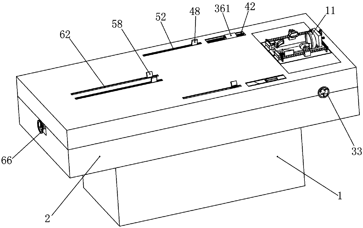
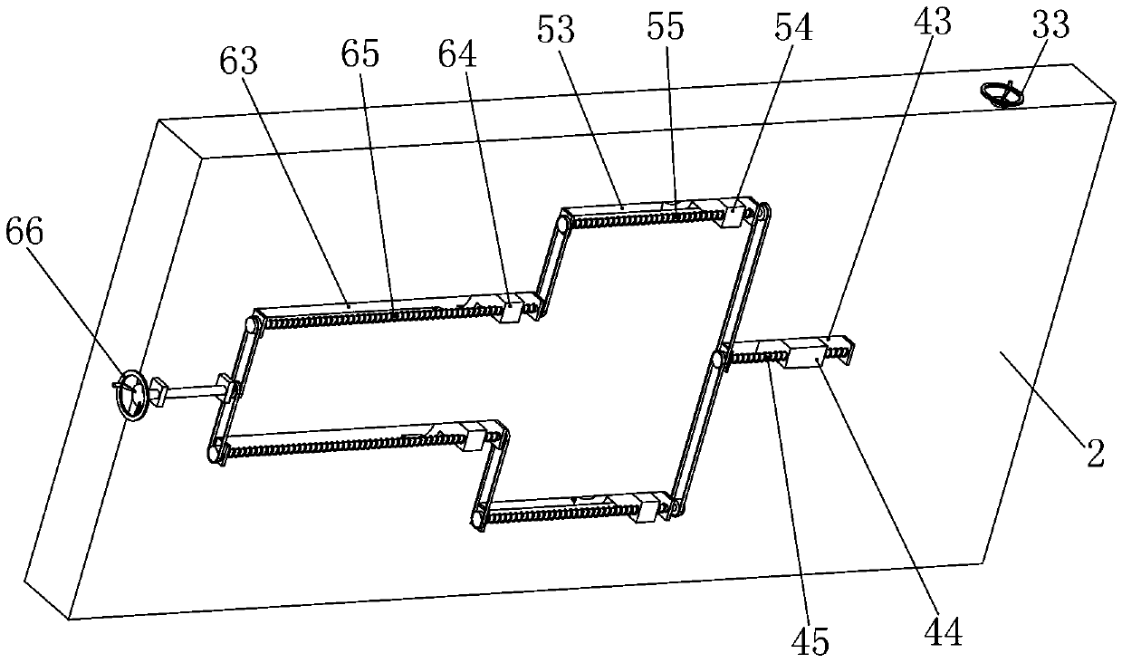
[0045] Embodiment 1, the present invention is a fixing device for nuclear magnetic resonance examination, including a base 1, the base 1 can be fixed on the bottom surface, a bed board 2 is slidably installed on the base 1, and the bed board 2 can slide left and right on the base 1 , the 2-bit follow-up structure of the bed board provides a fixed foundation. It is characterized in that a head fixing device is installed on the right end of the bed board 2, and the head fixing device can fix the patient's head. The chest fixing device and the hand fixing device on the left side of the device, the chest fixing device and the hand fixing device can fix the patient's chest and hands, the left end of the bed board 2 is equipped with a leg fixing device, the leg fixing device can The patient's legs are fixed, and an adjustment device located inside the bed board 2 is connected under the head fixation device. When the patient struggles hard, the head fixation device will be offset, and...
Embodiment 2
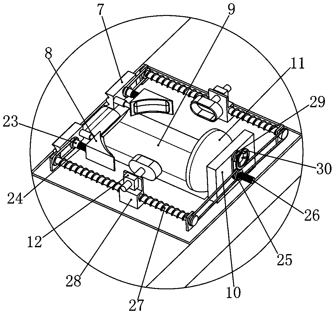
[0052] Embodiment 2. On the basis of Embodiment 1, cheek rest sleeves 23 are installed on the right end surfaces of the two shoulder rests 7 rotatably. The chin rest threaded rod 24 connected to the two chin rests 8, the two chin rest sleeves 23 can rotate on the two shoulder rests 7 respectively, and when rotating, the two chin rest threaded covers 24 can drive the two chin rests 8 Move left and right, when the two chin rests 8 move to the right, they can withstand the cheeks on both sides of the patient to the right, and the right end surface of the vertical plate 10 is rotated with a headgear sleeve 25, and the headgear sleeve 25 is internally threaded. Connected with the headgear threaded rod 26 that runs through the riser 10, the left end of the headgear threaded rod 26 is connected with the headgear 11, the headgear sleeve 25 can rotate on the riser 10, and can make the headgear threaded with it when rotating The threaded rod 26 drives the headgear 11 to move left and ri...
Embodiment 3
[0055] Embodiment 3, on the basis of Embodiment 2, the head installation groove 3 is rotatably installed with a lifting screw 31 placed front and back and located under the head lifting shell 4, and the direction of the thread line at both ends of the lifting screw 31 is On the contrary, and can rotate in the head installation groove 3, the wedge-shaped slide block 32 that is positioned at the two ends of head installation groove 3 bottom face front and back is threaded on the described lifting screw 31, the slope of two described wedge-shaped slide blocks 32 is upward, And the head lifting shell 4 is placed on the slope of the two wedge-shaped sliders 32. When the lifting screw 31 rotates, the threads at both ends cooperate with the two wedge-shaped sliders 32 and drive the two wedge-shaped sliders 32 to the head. The middle part of the groove 3 moves, and when the two wedge-shaped sliders 32 move to the middle, the head lifting shell 4 can be lifted up, and the lifting of the...
PUM
 Abstract
Description
Claims
Application Information
 - R&D
- Intellectual Property
- Life Sciences
- Materials
- Tech Scout
- Unparalleled Data Quality
- Higher Quality Content
- 60% Fewer Hallucinations
Browse by: Latest US Patents, China's latest patents, Technical Efficacy Thesaurus, Application Domain, Technology Topic, Popular Technical Reports.
© 2025 PatSnap. All rights reserved.Legal|Privacy policy|Modern Slavery Act Transparency Statement|Sitemap|About US| Contact US: help@patsnap.com


