
High-precision distributed optical fiber frequency transfer method

A distributed optical fiber and frequency transmission technology, applied in transmission systems, wavelength division multiplexing systems, electromagnetic wave transmission systems, etc., can solve problems such as backscattering symmetry system complexity, and achieve unlimited dynamic range and good long-term stability , to ensure the effect of symmetry

Active Publication Date: 2017-04-26
SHANGHAI JIAO TONG UNIV
View PDF3 Cites 20 Cited by
  • Summary
  • Abstract
  • Description
  • Claims
  • Application Information

AI Technical Summary

Problems solved by technology

In order to achieve a high-performance and low-cost solution, we need to solve problems such as backscattering, symmetry, and system complexity. Existing solutions basically fail to take care of these aspects at the same time

Method used


Image

  • High-precision distributed optical fiber frequency transfer method
  • High-precision distributed optical fiber frequency transfer method
  • High-precision distributed optical fiber frequency transfer method

Examples


Embodiment Construction

[0026] The present invention will be further described below in conjunction with drawings and embodiments. The examples are carried out on the premise of the technical solutions of the present invention, and detailed implementation methods and processes are given, but the protection scope of the present invention is not limited to the following examples.

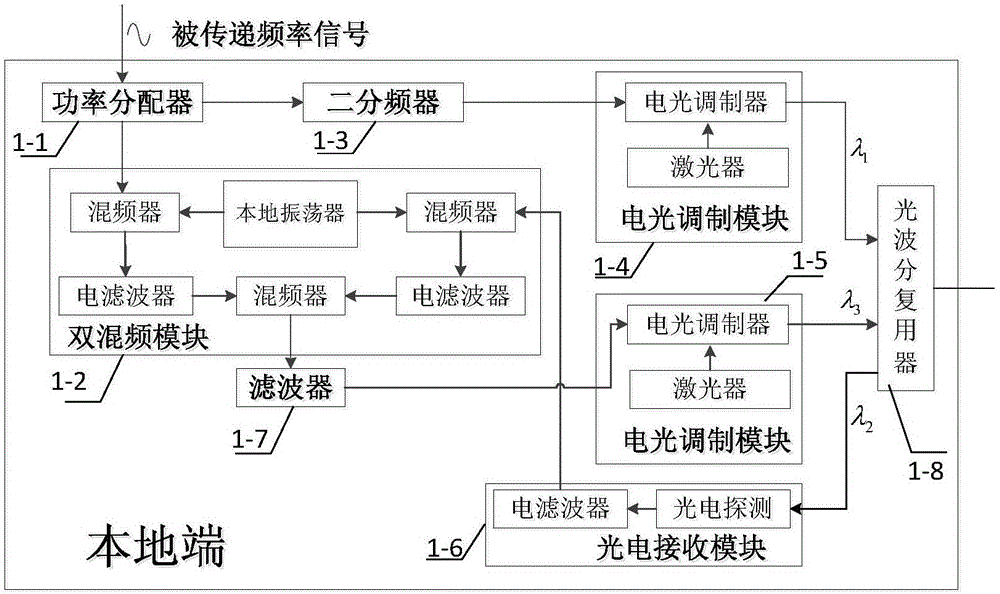
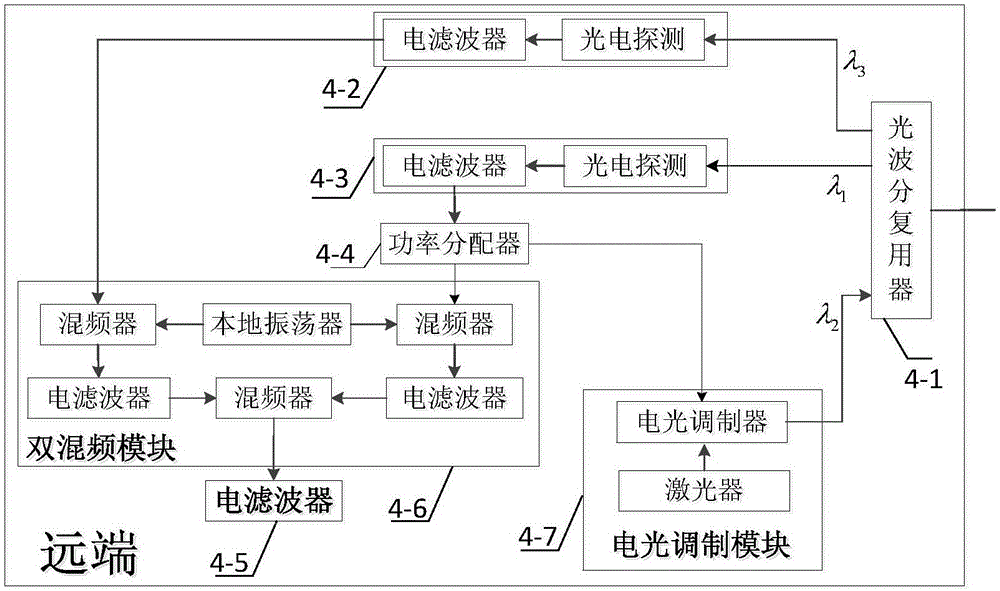
[0027] The block diagram of the system structure of this embodiment is as follows figure 1 As shown, it includes: a local end 1, an optical fiber link 2, multiple user ends 3, and a remote end 4. The local end 1 and the remote end 4 are located at both ends of the optical fiber link 2, and multiple user ends 3 are connected to the optical fiber link through optical coupling modules.

[0028] The local terminal 1 as described in figure 2 shown. The transmitted frequency signal is divided into two paths by the power divider 1-1. One way is input to the double frequency mixing module 1-2, and the other way is to generate a...


PUM


Abstract

The invention discloses a high-precision distributed optical fiber frequency transfer method. Local transferred frequency signals are subjected to frequency halving and then serve as detection signals, the signals are transmitted back and forth between the local end and a remote end through bidirectional wavelength division multiplexing, and detection signals comprising optical fiber link phase noise are obtained at the local end; the returned detection signals and the local transferred frequency signals are subjected to frequency mixing and filtering to obtain phase conjugation signals, and the phase conjugation signals are transmitted to the optical fiber link through another wavelength channel; all users detect forward conjugation signals and backward detection signals, and stable frequency signals are obtained through frequency mixing; and the remote end carries out frequency mixing on the received forward phase conjugation signals and the forward detection signals to obtain stable frequency signals. Influences on frequency transfer short-term stability by backscattering noise can be avoided; the users share the same wavelength, and the fiber frequency long-term stability influences and the cost due to increasing of users can be reduced; and by adopting passive compensation, the method has the advantages of relatively simple and unlimited dynamic range and quick compensation.

Description

technical field [0001] The invention relates to the technical field of optical fiber time-frequency transmission, in particular to a distributed optical fiber frequency transmission method. Background technique [0002] In recent years, with the continuous development of science and technology, the stability of atomic frequency standards has been greatly improved. At the same time, many fields such as deep space exploration, particle accelerators, navigation and communication, and defense applications such as array radars have an increasing demand for high-stability frequency sources and long-distance frequency synchronization. However, these high-stable frequency sources are very expensive, usually huge in size and need to operate in an ideal environment, so long-distance transmission of high-stable frequency signals and long-distance signal synchronization are of great significance. [0003] Traditional frequency transmission schemes mainly include frequency transmission ...

Claims


Application Information

Patent Timeline
IPC IPC(8): H04B10/516H04B10/572H04B10/2537H04J14/02
CPCH04B10/2537H04B10/516H04B10/572H04J14/0278
Inventor 吴龟灵李洪伟张佳朋
Owner SHANGHAI JIAO TONG UNIV
Learn More