
High-precision optical fiber microwave frequency transmission system

A technology of microwave frequency and transmission system, which is applied in the direction of electromagnetic wave transmission system, optical fiber transmission, transmission system, etc., can solve problems such as asymmetry of transmission delay, asymmetry of transmission delay, and influence on long-term stability of signals, so as to avoid future The effect of scattering, the effect of ensuring symmetry

Active Publication Date: 2018-04-13
SHANGHAI JIAO TONG UNIV
View PDF7 Cites 11 Cited by
  • Summary
  • Abstract
  • Description
  • Claims
  • Application Information

AI Technical Summary

Problems solved by technology

However, the transmission of different wavelength optical carriers will cause the asymmetry of the forward and backward transmission delays, which will affect the long-term stability of the frequency signal when the transmission distance increases or the temperature changes greatly.
[0005] A simple way is to use different wavelengths of light to transmit to different user ends, but this requires multi-channel optical signals on the one hand, and on the other hand will cause the asymmetry of the transmission delay mentioned above

Method used


Image

  • High-precision optical fiber microwave frequency transmission system
  • High-precision optical fiber microwave frequency transmission system
  • High-precision optical fiber microwave frequency transmission system

Examples


Embodiment Construction

[0043] The present invention will be further described below in conjunction with drawings and embodiments. Since Form 1 and Form 2 of the present invention are similar in structure, the embodiment is implemented on the premise of the technical solution of Form 1 of the present invention, and detailed implementation methods and processes are provided, but the protection scope of the present invention is not limited to the following the embodiment.

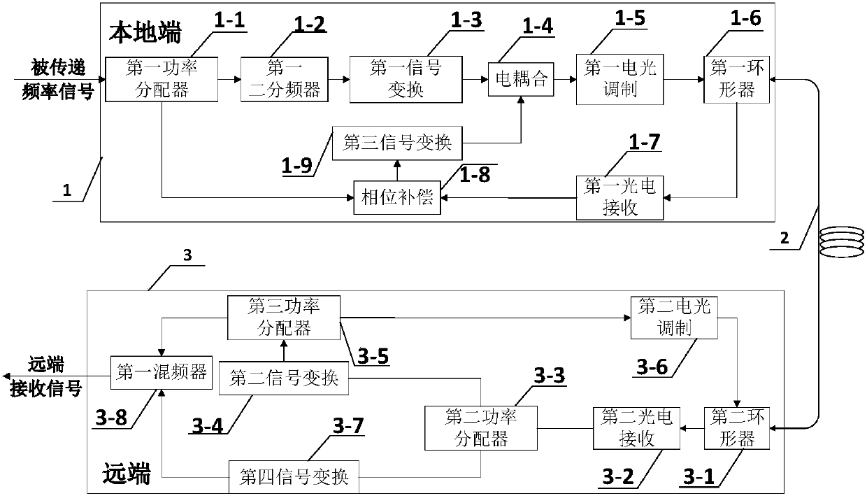
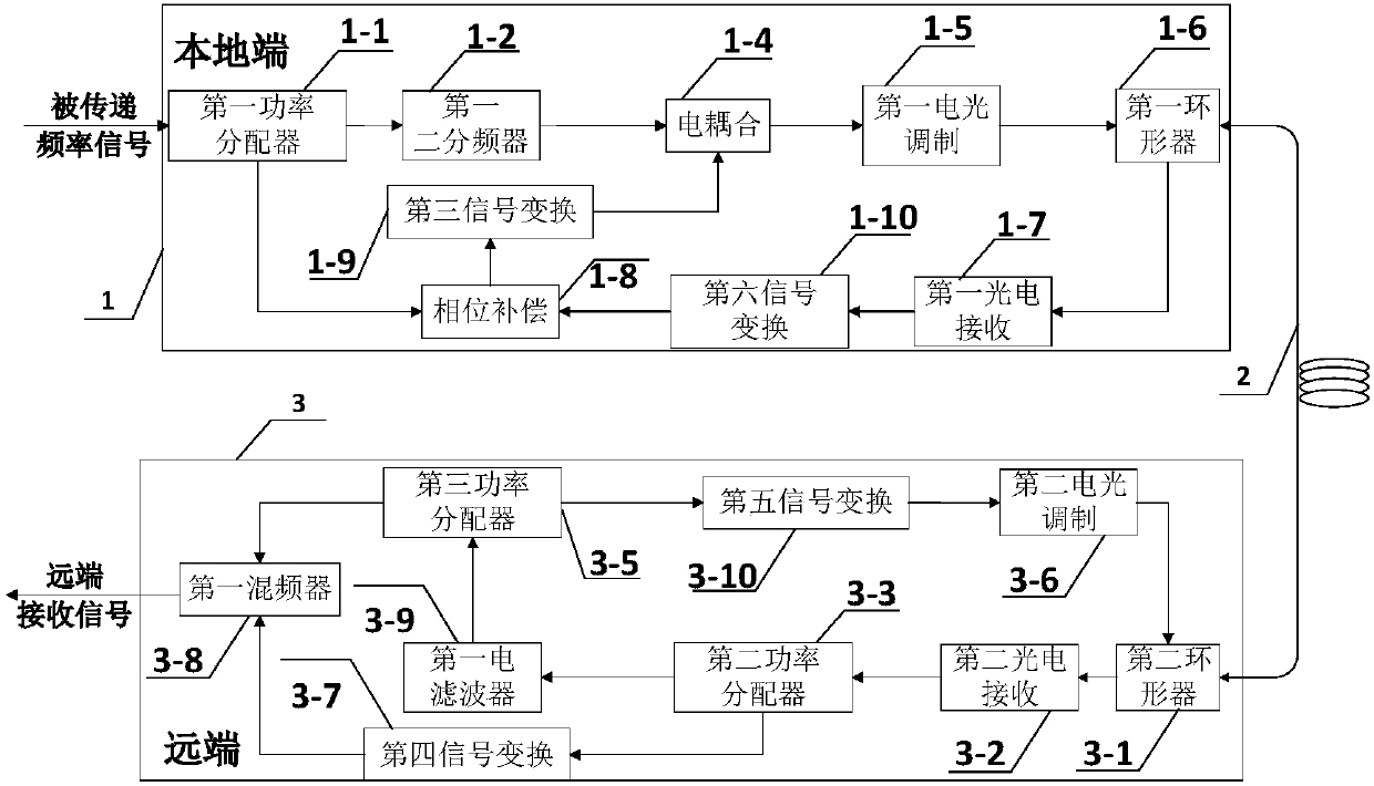
[0044] Please see first figure 1 , figure 1 It is a structural block diagram of Embodiment 1 of the high-precision active optical fiber microwave frequency transmission system of the present invention, at the local end, such as Figure 7 , the transmitted signal I with frequency f is divided into two paths by the first power divider 1-1, one path is signal II, and the other path is signal III. Among them, the signal III passes through the frequency divider 1-2 and the output frequency is The signal IV of f, the signal IV is sen...


PUM


Abstract

The invention relates to a high-precision optical fiber microwave frequency transmission system, which comprises a local end, an optical fiber link and a far end, wherein the local end and the far endare connected through the optical fiber link; the local end sends a forward signal, the far end receives the forward signal and returns the signal to the local end, the local end processes a to-be-transmitted frequency signal and a backward signal, generates a signal which is conjugated with phase jitter introduced by the one-way optical fiber link and sends the forward conjugated signal to the far end. The forward conjugated signal received by the far end is a stable microwave frequency signal. The high-precision optical fiber microwave frequency transmission system avoids influences of backscattering noise through a method of frequency conversion, thereby improving the signal-to-noise ratio, and being conducive to improving the short-term stability of frequency transmission; and meanwhile, forward and backward transmission share the same fiber and wave, so that wavelength asymmetry introduced by using wavelength division multiplexing is eliminated, and influences imposed on the long-term stability of frequency transmission by the wavelength interval are avoided.

Description

technical field [0001] The invention relates to the technical field of optical fiber time-frequency transmission, in particular to a high-precision optical fiber microwave frequency transmission system. Background technique [0002] As a basic physical quantity, time frequency has been widely used in deep space scientific research, determination of fundamental physical constants, and standard distribution of high-precision clocks. In recent years, various countries (especially developed countries) have invested heavily in related high-tech to support their development. With the application of new technologies, the indicators of existing frequency standards have been continuously improved, and their performance has been improved by an order of magnitude in about 7 to 10 years. At present, the best microwave clock reference source is an atomic clock based on cesium, and its long-term frequency instability is within 10 -16 order of magnitude. The principle of high-stability a...

Claims


Application Information

Patent Timeline
Patent Type & Authority Applications(China)
IPC IPC(8): H04B10/2537H04B10/25H04B10/077H04B10/516H04B10/69
CPCH04B10/0775H04B10/2537H04B10/2589H04B10/5165H04B10/697
Inventor 吴龟灵张佳朋林天成陈建平
Owner SHANGHAI JIAO TONG UNIV
Learn More