
Elevator internet-of-things intelligent box and system

A technology for elevator objects and smart boxes, which is applied to transmission systems, communication systems between relatively movable stations, electrical components, etc., can solve the problem of limiting the speed of image update, limiting the speed of data transmission, increasing material costs and production costs and other problems to achieve the effect of improving the data transmission rate, expanding the scope of use, and saving materials

Active Publication Date: 2017-04-26
SHANGHAI STEP ELECTRIC
View PDF7 Cites 5 Cited by
  • Summary
  • Abstract
  • Description
  • Claims
  • Application Information

AI Technical Summary

Problems solved by technology

[0006] 1. Each elevator needs two Wi-Fi converters. The internal AC-DC modules, circuit boards, peripheral devices and structural shells seriously increase the material cost and production cost.
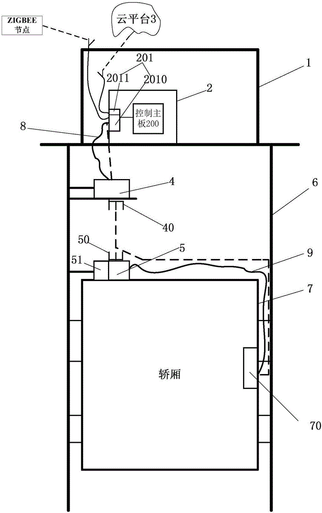
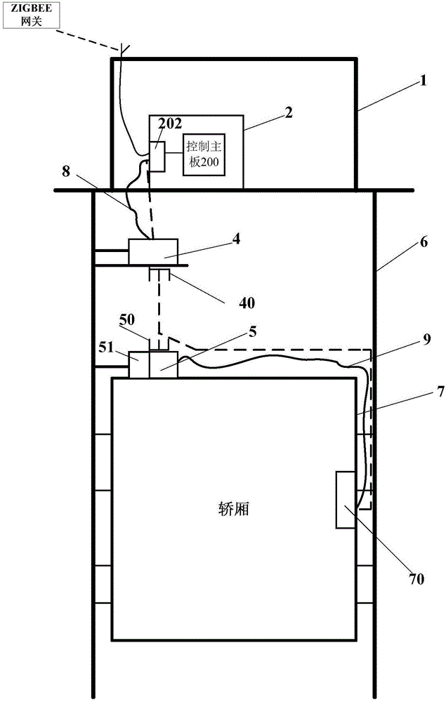
[0007] 2. There is a bottleneck in the data transmission link. For the data transmission of the Wi-Fi network, its transmission speed can reach more than 10 Mbps (megabits per second). Two RS232 adapter cables (8, 9) limit the speed of data transmission, which may easily cause a delay that can be felt by human eyes between the content displayed by the multimedia terminal 70 and the actual data, and limit the speed of image update at the same time
[0008] 3. Due to the barrier between the top of the hoistway 6 and the wall of the machine room 1 and the barrier between the top of the car 7 and the interior of the car, the Wi-Fi network can only transmit data inside the hoistway 6, while the after-sales debugging in the machine room 1 Personnel, maintenance personnel, passengers in car 7 or debugging maintenance personnel cannot effectively use the Wi-Fi network, which limits the scope of use of the Wi-Fi network of the elevator Internet of Things
For example, when a person is trapped in an elevator, the data link between the Wi-Fi network and the mobile network cannot be effectively used for remote intercom for help

Method used


Image

  • Elevator internet-of-things intelligent box and system
  • Elevator internet-of-things intelligent box and system
  • Elevator internet-of-things intelligent box and system

Examples


Embodiment Construction

[0030] In order to make the object, technical solution and advantages of the present invention clearer, various embodiments of the present invention will be described in detail below in conjunction with the accompanying drawings. However, those of ordinary skill in the art can understand that, in each implementation manner of the present invention, many technical details are provided for readers to better understand the present application. However, even without these technical details and various changes and modifications based on the following implementation modes, the technical solution claimed in this application can also be realized.

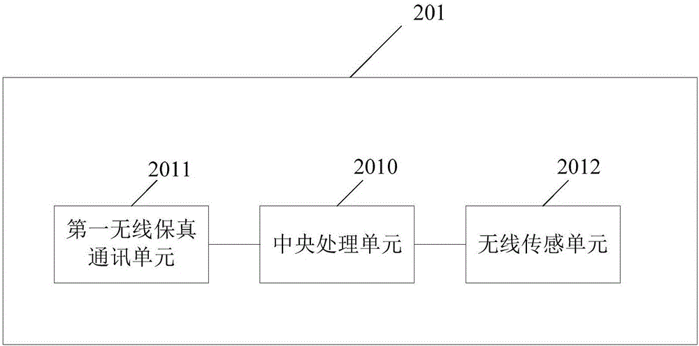
[0031] The first embodiment of the present invention relates to an elevator IoT smart box. Its specific structure is as image 3 shown.

[0032]Specifically, the elevator Internet of Things smart box 201 is used in the elevator machine room, and in practical applications, it can be set in the control cabinet of the elevator machine room. ...


PUM


Abstract

The invention relates to the elevator internet-of-things technology field and discloses an elevator internet-of-things intelligent box and system. In the invention, the elevator internet-of-things intelligent box is arranged in an elevator room and comprises a central processing unit, a first wireless fidelity communication unit and a wireless sensing unit wherein the first fidelity communication unit and the wireless sensing unit are both communicatively connected to the central processing unit; and the antenna of the first fidelity communication unit is capable of extending from the elevator room to the elevator shaft. The embodiments of the invention further provide an elevator internet-of-things system. With the embodiments of the invention, it is possible to reduce the cost of the elevator internet-of-things and expand the use scope of WiFi network of the elevator internet-of-things system.

Description

technical field [0001] The invention relates to the technical field of the elevator Internet of Things, in particular to an elevator Internet of Things smart box and system. Background technique [0002] The rapid development of the Internet of Things has involved the elevator industry, and the networking of the elevator system can effectively monitor and manage the elevator. For a community, the existing elevator IoT system is divided into: a gateway system and a node system. like figure 1 As shown, the gateway system includes: a control device 20 arranged in the control cabinet 2 in the machine room 1, the control device 20 includes a connected control main board 200 and an integrated board 201, and the integrated board 201 includes a communication-connected gateway board 2010 and data The transmission unit DTU (Data TransferUnit, data transmission unit) 2011. Wherein, the gateway board 2010 is, for example, a Zigbee (ZIGBEE) gateway, and the DTU, for example, may be a ...

Claims


Application Information

Patent Timeline
IPC IPC(8): H04L29/08H04B3/60B66B5/00
CPCH04B3/60H04L67/12B66B5/0018B66B5/0025Y02B50/00
Inventor 杜超林开伟王鹏
Owner SHANGHAI STEP ELECTRIC
Learn More