Supercharge Your Innovation With Domain-Expert AI Agents!

DLP configuration method, remote control, display unit and DLP configuration system

A technology of display unit and configuration method, which is applied in the direction of transmission system, signal transmission system, non-electrical signal transmission system, etc., and can solve the problem of slow response speed of DLP configuration

Inactive Publication Date: 2017-04-26
GUANGDONG VTRON TECH CO LTD
View PDF7 Cites 0 Cited by
  • Summary
  • Abstract
  • Description
  • Claims
  • Application Information

AI Technical Summary

Problems solved by technology

[0004] The embodiment of the present invention provides a DLP configuration method, a remote controller, a display unit, and a system. After the DLP system is built, it is necessary to configure the ip, system number, and unit number (the location of the unit) of all units in the system. Now If there is a unit ip conflict in the technical system (multiple units use the same ip), it must be manually checked and set to ensure that the ip of each unit is different, and after ensuring that the ip of each unit in the system is different, then confirm the number of each unit Basically, it is necessary to manually or cooperate with the software to confirm the real location of the system where the unit ip is located (the row and column of the system where the unit is located), and configure the unit number of the ip unit, which leads to the slow response speed of the existing DLP configuration technical problem

Method used


Image

  • DLP configuration method, remote control, display unit and DLP configuration system
  • DLP configuration method, remote control, display unit and DLP configuration system
  • DLP configuration method, remote control, display unit and DLP configuration system

Examples


Embodiment Construction

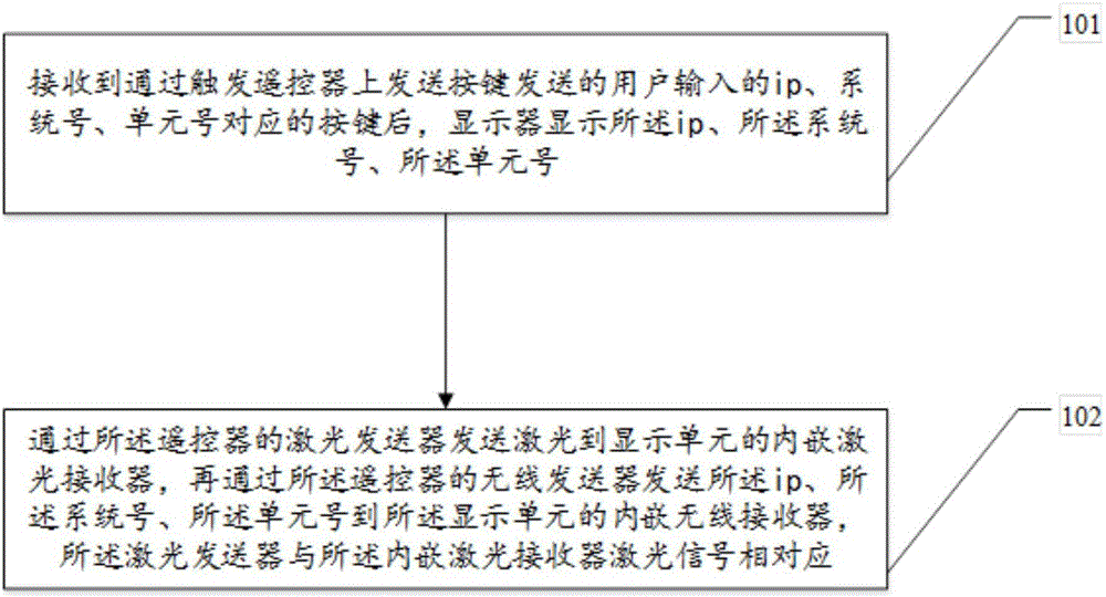
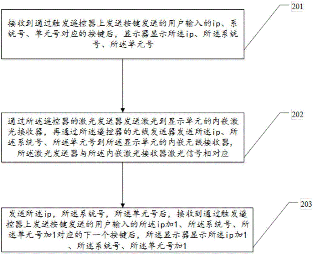
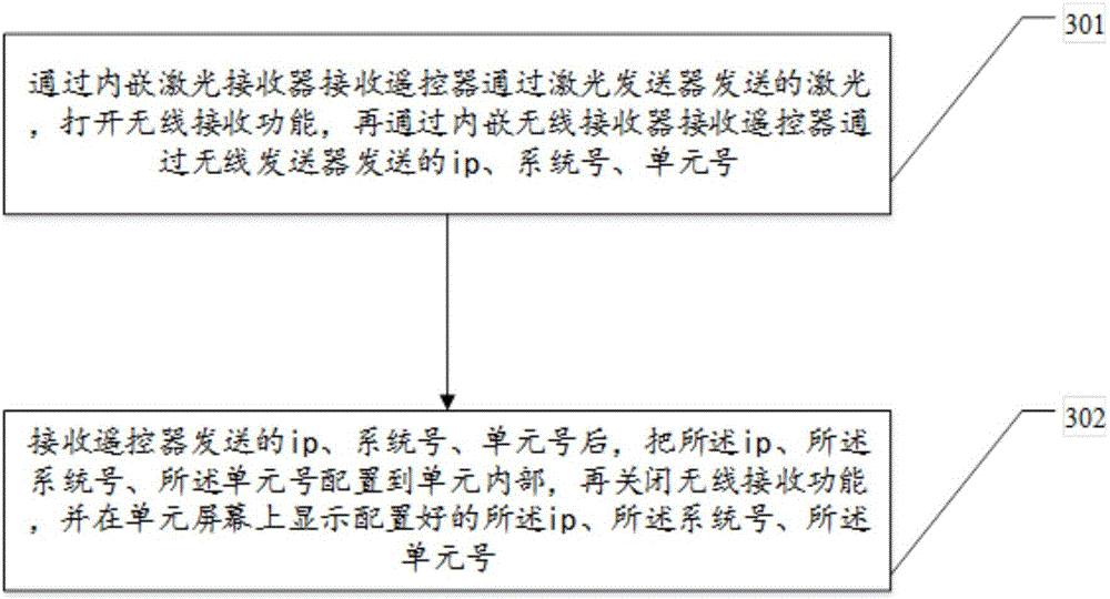
[0048]The embodiment of the present invention provides a DLP configuration method, a remote controller, a display unit, and a system. After the DLP system is built, it is necessary to configure the ip, system number, and unit number (the location of the unit) of all units in the system. Now If there is a unit ip conflict in the technical system (multiple units use the same ip), it must be manually checked and set to ensure that the ip of each unit is different, and after ensuring that the ip of each unit in the system is different, then confirm the number of each unit Basically, it is necessary to manually or cooperate with the software to confirm the real location of the system where the unit ip is located (the row and column of the system where the unit is located), and configure the unit number of the ip unit, which leads to the slow response speed of the existing DLP configuration technical problem.

[0049] In order to make the purpose, features and advantages of the pres...


PUM


Abstract

The embodiments of the invention disclose a DLP configuration method, a remote control, a display unit and a DLP configuration system. After a DLP system is completed, there is a need to configure the IP, system number and unit number (location) of all the units of the system. In the prior art, if there is a unit IP conflict in the system (multiple units use the same IP), the units must be artificially checked and reset to ensure that the IPs of all the units are different. For confirmation of the IP of each unit after that the IPs of all the units are different is ensured, there is a need to confirm the real location of the IP of the unit in the system (the row in which the unit is located in the system and the column in which the unit is located in the system) and configure the unit number of the IP unit artificially or with the aid of software. Thus, the existing DLP system responds slowly in configuration. By using the DLP configuration method, the remote control, the display unit and the DLP configuration system, the technical problem in the prior art is solved.

Description

technical field [0001] The invention relates to the field of system configuration, in particular to a DLP configuration method, a remote controller, a display unit and a system. Background technique [0002] After the DLP system is built, it is necessary to configure the ip, system number, and unit number (the location of the unit) of all units in the system. [0003] If there is a unit ip conflict in the system (multiple units use the same ip), it must be manually checked and set to ensure that the ip of each unit is different; after ensuring that the ip of each unit in the system is different, when confirming the number of each unit, it is basically necessary to Manually or with software to confirm the real location of the system where the unit ip is located (the row and column of the system where the unit is located), and configure the unit number of the ip unit. After completing the above two steps, the ip of all units in the system is not continuous at this time Yes, a...

Claims


Application Information

Patent Timeline
IPC IPC(8): H04L29/12G08C23/04G08C17/02
CPCH04L61/3005G08C17/02G08C23/04
Inventor 吴施烙
Owner GUANGDONG VTRON TECH CO LTD
Features
  • R&D
  • Intellectual Property
  • Life Sciences
  • Materials
  • Tech Scout
  • Unparalleled Data Quality
  • Higher Quality Content
  • 60% Fewer Hallucinations
Learn More