LED driving power supply flow measurement circuit and method

A technology of LED drive and drive circuit, which is applied in the direction of electric light source, electroluminescent light source, light source, etc., and can solve the problems of high cost of repeated design, single index of current measurement circuit, poor versatility, etc.

Active Publication Date: 2017-04-26
DELIGHT INNOVATIVE TECH LTD
View PDF4 Cites 1 Cited by
  • Summary
  • Abstract
  • Description
  • Claims
  • Application Information

AI Technical Summary

Problems solved by technology

[0003] The present invention aims at the problem that the current measurement circuit of the existing LED drive power supply cannot be applied to different load ranges due to the use of a constant current source, and the existing current measurement circuit has a single index and poor versatility, thus resulting in high repeated design costs. A new type of current measurement circuit for LED drive power supply. Through the reasonable configuration of resistance and multi-input control circuit, the circuit realizes the accurate current measurement and feedback function, and at the same time realizes the application of current measurement circuit to different load applications, and improves the Improve the versatility of the current measurement circuit, reduce the design cycle and cost

Method used


Image

  • LED driving power supply flow measurement circuit and method
  • LED driving power supply flow measurement circuit and method

Examples


Embodiment Construction

[0020] The present invention will be described below in conjunction with the accompanying drawings.

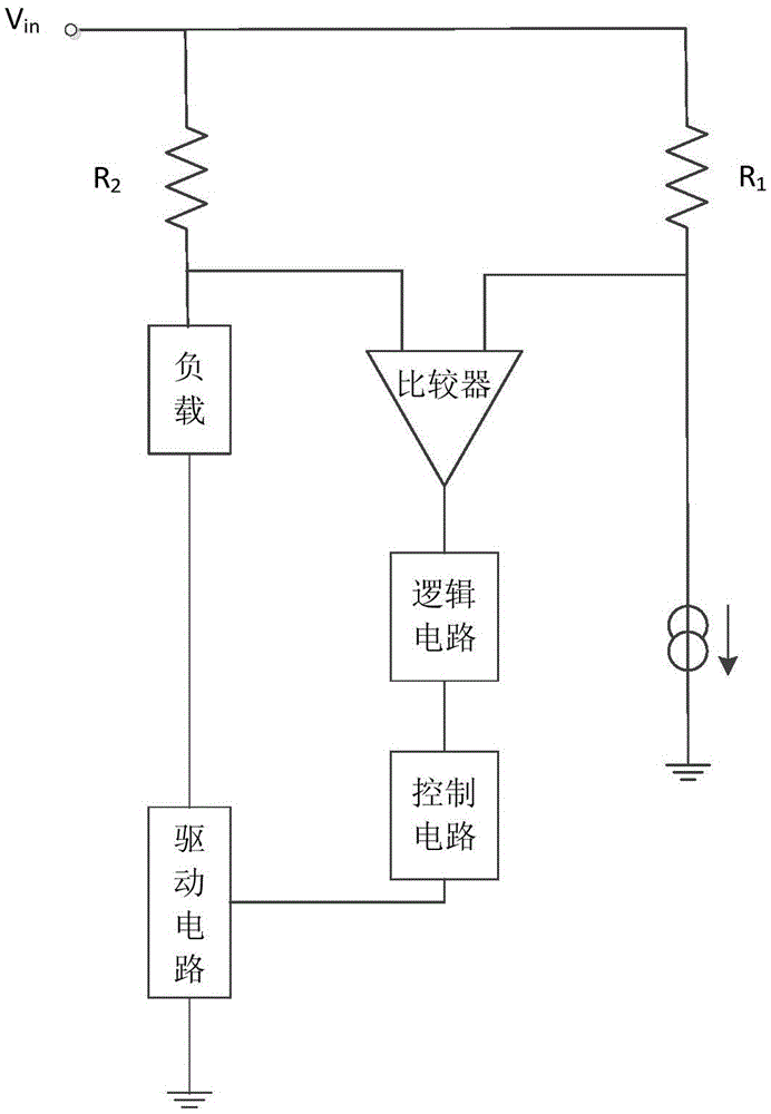
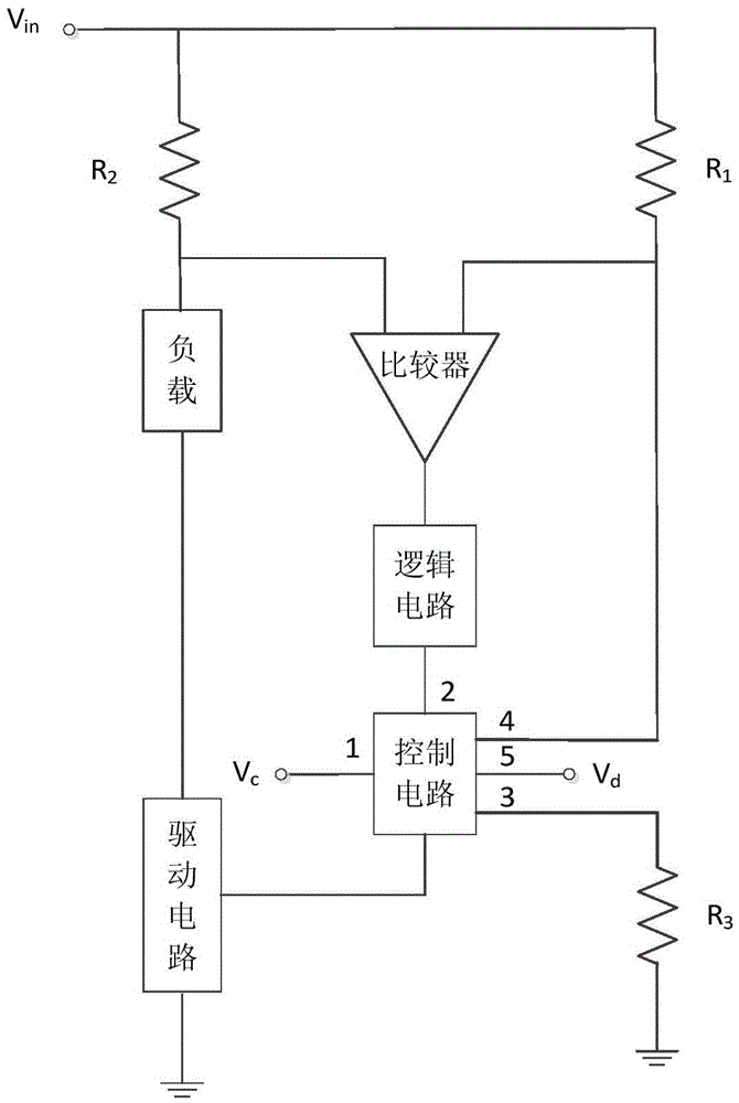
[0021] The present invention relates to a current measuring circuit of LED drive power supply, the schematic diagram of the circuit structure is as follows: figure 2 shown, including the current limiting resistor R 1 , Measuring resistance R 2 , comparator, logic circuit, drive circuit and load, also includes control circuit and configuration resistor R 3 , the control circuit of this embodiment has five input terminals and one output terminal, where the current limiting resistor R 1 One end of the input supply V in connection, the current limiting resistor R 1 The other end of the comparator is connected to an input end of the comparator (such as the non-inverting input end) and the fourth input end of the control circuit at the same time, and the current measuring resistance R 2 One end of the input supply V in connection, the current sense resistor R 2 The other end...


PUM


Abstract

The present invention provides a LED driving power supply flow measurement circuit and method. The flow measurement circuit comprises a current-limiting resistor, a flow measurement resistor, a comparator, a logic circuit, a driving circuit and a load. The flow measurement circuit also comprises a control circuit and a configuration resistor. One end of the current-limiting resistor and one end of the flow measurement resistor are connected with an input power supply, the other end of the current-limiting resistor is connected with one input end of the comparator and the fourth input end of the control circuit, the other end of the flow measurement resistor is connected with the other end of the comparator and the output end of the load, the output end of the comparator is connected with the input end of the control circuit through the logic circuit, the input end of the load is connected with the output end of the driving circuit, the first input end of the control circuit inputs control voltage signals, the third input end of the control circuit is connected with one end of the configuration resistor, and the output end of the control circuit is connected with the input end of the driving circuit. The flow measurement circuit can realize the accurate flow measurement feedback function, and is applied to different load applications so as to improve the universality of the flow measurement circuit and reduce the cost.

Description

technical field [0001] The invention relates to the technical field of LED driving power supply, in particular to a novel current measuring circuit and method for LED driving power supply. Background technique [0002] LED drive power supply refers to the power converter that converts the power supply (such as high-voltage industrial frequency AC or mains power, low-voltage high-frequency AC such as the output of electronic transformers, etc.) into a specific voltage and current to drive LED lighting equipment or devices to emit light. That is to say, the power supply is converted to the rated power suitable for the operation of lighting equipment or devices through devices such as transformers. In order to ensure the safe use of the LED drive power supply, a control circuit is generally configured in the LED drive power supply, and the control circuit controls the LED drive power supply according to the corresponding current measurement feedback results. The traditional cu...

Claims


Application Information

Patent Timeline
Patent Type & Authority Applications(China)
IPC IPC(8): H05B33/08H05B44/00
CPCH05B45/00H05B45/395
Inventor 尤建兴
Owner DELIGHT INNOVATIVE TECH LTD
Why Eureka
Try Eureka