Smashing and grinding device used in garbage fertilizer making system

A grinding device and garbage technology, applied in the direction of pressure inorganic powder coating, grain processing, etc., can solve problems such as unfavorable operation of fertilizer system, difficulty in separation and crushing, increase in cost, etc., and achieve good crushing and grinding effect, short cycle, increase The effect of the service life

Inactive Publication Date: 2017-05-03
JIANGSU QINGSHI TECH
View PDF9 Cites 7 Cited by
  • Summary
  • Abstract
  • Description
  • Claims
  • Application Information

AI Technical Summary

Problems solved by technology

[0002] At present, with the development of society, garbage disposal seriously restricts economic development. There are a lot of garbage in streets, alleys, and various restaurants. At that time, in the waste fertilizer system, separation and crushing were the most difficult processes. There were a lot of extremely difficult to crush waste, which often caused blockage and damage to equipment, increased costs, and was not conducive to the normal operation of the fertilizer system.

Method used


Image

  • Smashing and grinding device used in garbage fertilizer making system
  • Smashing and grinding device used in garbage fertilizer making system
  • Smashing and grinding device used in garbage fertilizer making system

Examples


Embodiment 1

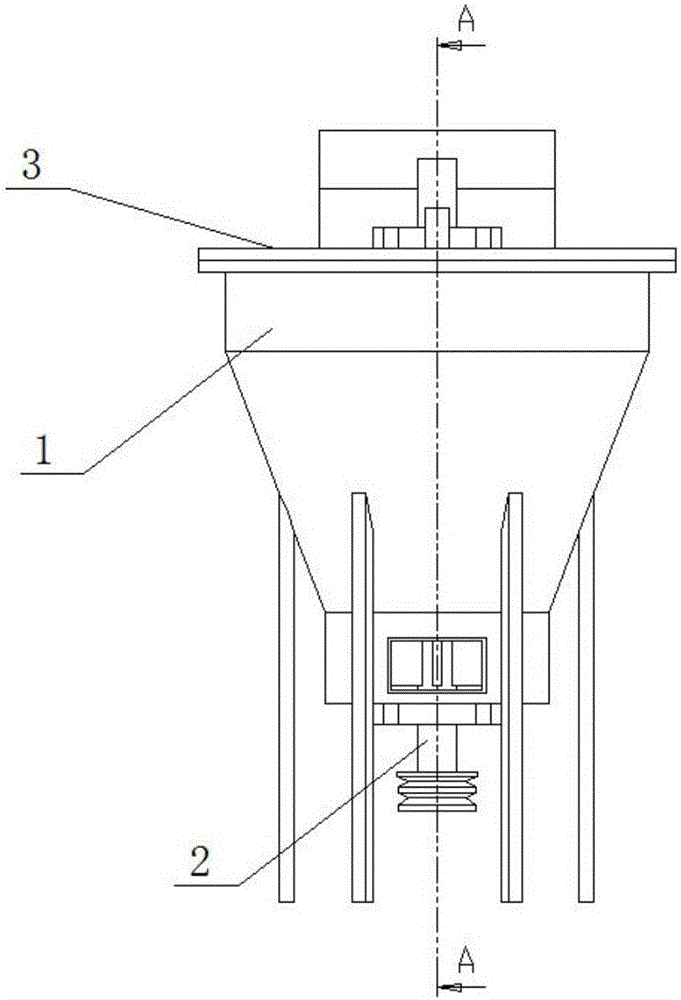
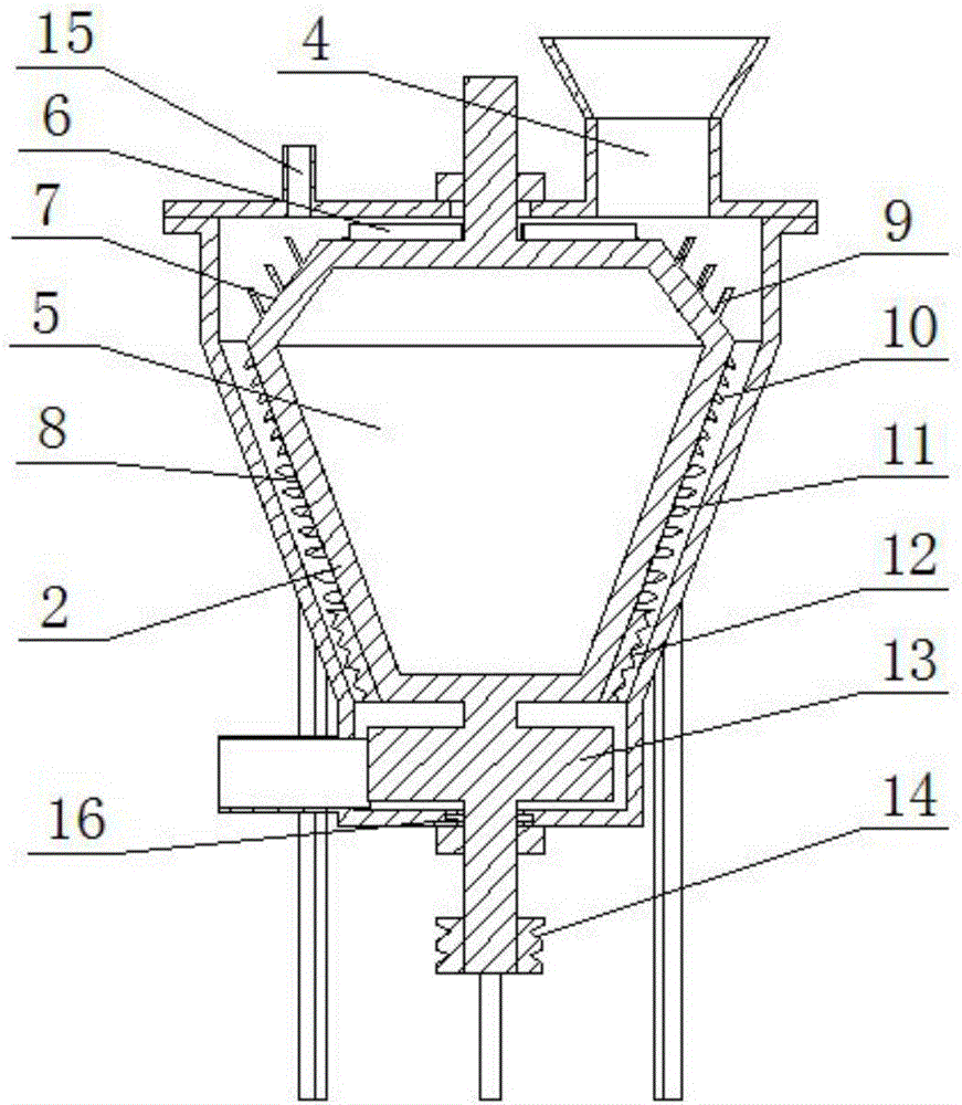
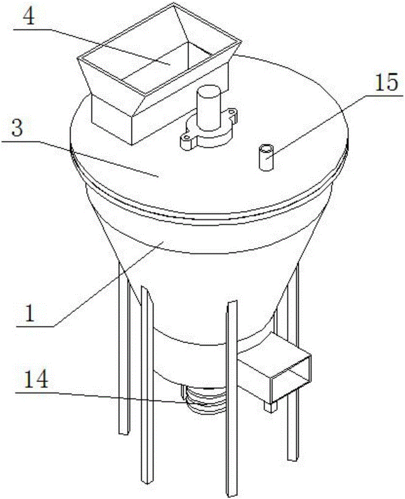
[0029] The crushing and grinding device used in the garbage fertilizer system provided by this embodiment includes a horizontally placed machine base 1, the cross section of the machine base 1 is in a "V" shape, and the inside of the machine base 1 is vertically provided with a crushing roller 2, The shape of the crushing roller 2 matches the machine base 1. The upper end of the machine base 1 is provided with an end cover 3 for fixing the crushing roller 2. The end cover 3 is provided with a feed port 4 and a water inlet 15. The inside of the crushing roller 2 is empty. The cavity 5 is horizontally provided with a uniform material plate 6 on the upper end surface of the crushing roller 2, and the outer surface of the crushing roller 2 is provided with a blanking surface 7 and a crushing surface 8 in sequence from top to bottom, and the blanking surface 7 and the crushing surface 8 are all inclined. The first crushing knife 9 is arranged on the cutting surface 7, and the cuttin...

Embodiment 2

[0037] The crushing and grinding device used in the garbage fertilizer system provided by this embodiment includes a horizontally placed machine base 1, the cross section of the machine base 1 is in a "V" shape, and the inside of the machine base 1 is vertically provided with a crushing roller 2, The shape of the crushing roller 2 matches the machine base 1. The upper end of the machine base 1 is provided with an end cover 3 for fixing the crushing roller 2. The end cover 3 is provided with a feed port 4 and a water inlet 15. The inside of the crushing roller 2 is empty. The cavity 5 is horizontally provided with a uniform material plate 6 on the upper end surface of the crushing roller 2, and the outer surface of the crushing roller 2 is provided with a blanking surface 7 and a crushing surface 8 in sequence from top to bottom, and the blanking surface 7 and the crushing surface 8 are all inclined. The first crushing knife 9 is arranged on the cutting surface 7, and the cuttin...

Embodiment 3

[0045] The crushing and grinding device used in the garbage fertilizer system provided by this embodiment includes a horizontally placed machine base 1, the cross section of the machine base 1 is in a "V" shape, and the inside of the machine base 1 is vertically provided with a crushing roller 2, The shape of the crushing roller 2 matches the machine base 1. The upper end of the machine base 1 is provided with an end cover 3 for fixing the crushing roller 2. The end cover 3 is provided with a feed port 4 and a water inlet 15. The inside of the crushing roller 2 is empty. The cavity 5 is horizontally provided with a uniform material plate 6 on the upper end surface of the crushing roller 2, and the outer surface of the crushing roller 2 is provided with a blanking surface 7 and a crushing surface 8 in sequence from top to bottom, and the blanking surface 7 and the crushing surface 8 are all inclined. The first crushing knife 9 is arranged on the cutting surface 7, and the cuttin...


PUM

PropertyMeasurementUnit
angleaaaaaaaaaa

Abstract

The invention discloses a smashing and grinding device used in a garbage fertilizer making system. The smashing and grinding device comprises a horizontally placed machine seat. The section of the machine seat is in a V shape. A smashing roller is vertically arranged in the machine seat. The shape of the smashing roller is matched with the machine seat. An end cover used for fixing the smashing roller is arranged at the upper end of the machine seat and is provided with a feed inlet. A cavity is arranged in the smashing roller. A material evening plate is horizontally arranged on the upper end face of the smashing roller. A discharge face and a smashing face are arranged on the outer surface of the smashing roller sequentially from top to bottom. The discharge face and the smashing face are both arranged obliquely. The discharge face is provided with a first crushing cutter. A smashing cutter set, a rough grinding cutter set and a fine grinding cutter set are arranged on the discharge face sequentially from top to bottom. The smashing cutter set comprises a plurality of smashing cutters. The smashing and grinding device is simple in structure, long in service life, convenient to operate, low in cost, safe, reliable, capable of fast and effectively smashing and grinding garbage, particularly some garbage difficult to smash, high in structural strength and wide in usage range.

Description

technical field [0001] The invention relates to a garbage treatment device, in particular to a crushing and grinding device used in a garbage fertilizer making system. Background technique [0002] At present, with the development of society, garbage disposal seriously restricts economic development. There are a lot of garbage in streets, alleys, and various restaurants. At that time, in the waste fertilizer system, separation and crushing were the most difficult processes. There were a lot of extremely difficult to crush garbage that often caused blockage and damage to equipment, which increased costs and was not conducive to the normal operation of the fertilizer system. Contents of the invention [0003] The technical problem to be solved by the present invention is to propose a crushing and grinding device used in the garbage fertilizer system, which not only has a simple structure, but also has a long service life, convenient operation, low cost, safety and reliabilit...

Claims


Application Information

Patent Timeline
Patent Type & Authority Applications(China)
IPC IPC(8): B02C18/28C22C38/06C22C38/02C22C38/10C22C38/08C22C38/04C22C38/12C23C24/04
CPCB02C18/28B02C2201/06C22C38/002C22C38/005C22C38/02C22C38/04C22C38/06C22C38/105C22C38/12C23C24/04
Inventor 万仁军
Owner JIANGSU QINGSHI TECH
Why Eureka
Try Eureka