
Gear-ring-unwinding high-speed counter-current chromatograph

A high-speed countercurrent chromatography and unwinding technology, which is applied in the field of separation and analysis instruments, can solve the problems of inability to adjust, poor instrument stability, and limited instrument functions, so as to broaden the scope of use, prolong the service life, and reduce the noise of the instrument. Effect

Active Publication Date: 2017-05-10
SHANDONG ANALYSIS & TEST CENT
View PDF10 Cites 3 Cited by
  • Summary
  • Abstract
  • Description
  • Claims
  • Application Information

AI Technical Summary

Problems solved by technology

[0004] The countercurrent chromatograph with this structure: 1. It is easy to cause excessive force on the central gear, and the long-term operation causes the central shaft where the central gear is located to shake, resulting in poor stability of the instrument; 2. At the same time, due to the existence of the revolving gear and the central shaft, the instrument The β value of β cannot be further increased, which leads to the limitation of the function of the instrument; 3. In the high-speed countercurrent chromatograph, the R size is an important parameter, and the R size of the conventional high-speed countercurrent chromatograph is usually fixed and cannot be adjusted. The design of the gear ring structure can adjust the size of the gears in the separation column and the unwinding shaft, so that it is convenient to adjust the R size and broaden the use range of the instrument

Method used


Image

  • Gear-ring-unwinding high-speed counter-current chromatograph
  • Gear-ring-unwinding high-speed counter-current chromatograph
  • Gear-ring-unwinding high-speed counter-current chromatograph

Examples


Embodiment 1

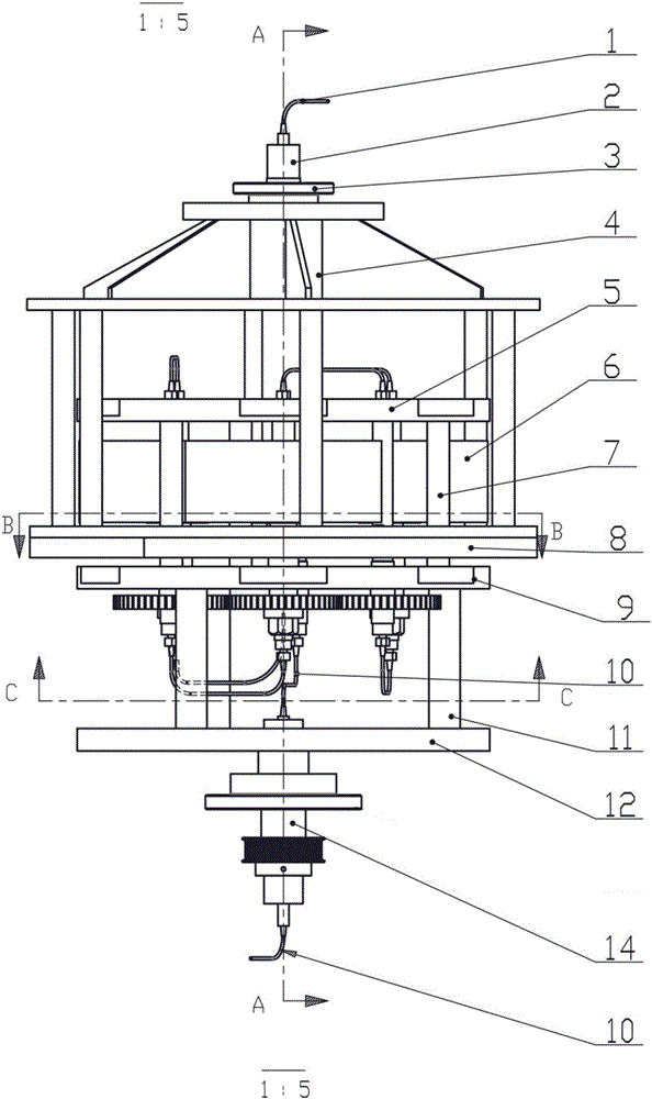
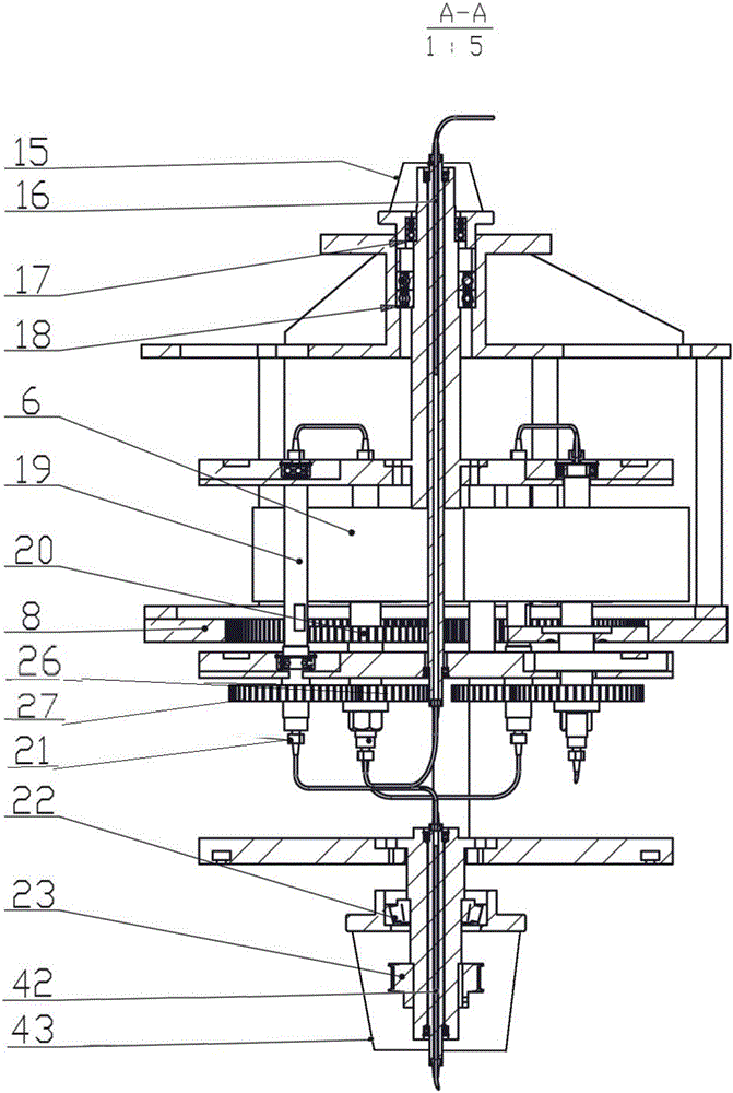
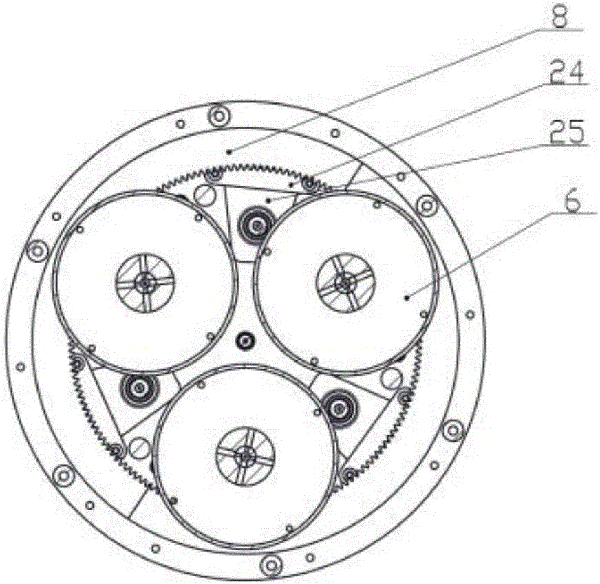
[0042] Such as Figure 1-2 As shown, a high-speed countercurrent chromatograph with unwound gear rings includes a rotating support, and the rotating support includes an upper plate 5, a middle plate 9 and a lower plate that are installed in sequence and connected into one body through a connecting column 7 and a connecting column 11. Disc 12, above the middle disc 9 is fixed with an unwinding gear ring 8 coaxial with it, the lower disc 12 is driven to rotate by a drive shaft 14, and the unwinding gear ring 8 is not fixed and the teeth of the unwinding gear ring 8 are distributed on its inner ring, and along the circumferential direction of the inner ring of the unwinding gear ring 8, there are a plurality of gears I20 meshed with it, and the gears I20 between adjacent groups are not meshed. The gear I20 drives the separation column to rotate, and a gear II26 is coaxially installed below each of the gears I20, the gear II26 meshes with the gear III27, and the gear III27 drives ...

Embodiment 2

[0054] Embodiment 2 The drawings of this embodiment are not shown in the drawings.

[0055] The high-speed countercurrent chromatograph with unwound gear rings includes a rotating support, and the rotating support includes an upper plate, a middle plate and a lower plate that are installed in sequence and connected into one body. The unwinding gear ring of the shaft, the lower plate drives its rotation through a drive shaft, the unwinding gear ring is fixed, and the teeth of the unwinding gear ring are distributed on its inner ring, and along the unwinding teeth There are multiple groups of gears meshing with the inner ring of the ring, and the gears between adjacent groups are not meshing. Each group of gears includes two gears that mesh with each other, one of which drives a separation column, and the other gear drives a solution. Around the shaft, the separation column is installed on a separation shaft, the upper end of the unwinding shaft and the separation shaft are conn...


PUM


Abstract

The invention discloses a gear-ring-unwinding high-speed counter-current chromatograph. The gear-ring-unwinding high-speed counter-current chromatograph comprises an upper plate, a middle plate and a lower plate, wherein an unwinding gear ring coaxial with the middle plate is fixed above the middle plate, the lower plate is driven to rotate through a drive shaft, the unwinding gear ring is fixed, the teeth of the unwinding gear ring are distributed on the inner ring of the unwinding gear, multiple groups of gears which mesh with the inner ring of the unwinding gear ring are arranged along the circumferential direction of the inner ring of the unwinding gear ring, gears of adjacent groups do not mesh with one another, each group of gears comprises two gears which mesh with each other, one gear of each group of gears drives one separation column, the other gear of each group of gears drives one unwinding shaft, each separation column is mounted on a separation shaft, the upper ends of each unwinding shaft and each separation shaft are connected with the upper plate, and the lower ends of each unwinding shaft and each separation shaft are connected with the middle plate; each unwinding shaft and each separation column rotate along with a rotation support; a liquid inlet pipe penetrates the central shafts of the upper plate and the middle plate and is serially connected with liquid conveying pipes of multiple groups of separation columns and unwinding shafts, and liquid finally is discharged from a liquid outlet pipe.

Description

technical field [0001] The invention relates to the field of separation and analysis instruments, in particular to a high-speed countercurrent chromatograph with an unwound gear ring. Background technique [0002] High-speed countercurrent chromatography is a liquid-liquid partition chromatography without solid support packing, and the separation is realized according to the difference in the distribution coefficient of the components to be separated in the upper and lower phases. The principle is to use the centrifugal force generated by the spiral tube during planetary motion to continuously mix the immiscible two-phase solvents, distribute the samples multiple times, and achieve separation according to the different partition coefficients of the substances to be separated. Because there is no need for any solid carrier or support, it can achieve high-efficiency separation and preparation in a short time, and can reach thousands of theoretical plates. Compared with other ...

Claims


Application Information

Patent Timeline
Patent Type & Authority Applications(China)
IPC IPC(8): B01D15/10B01D15/30
CPCB01D15/10B01D15/30G01N30/42
Inventor 王岱杰王晓耿岩玲于金倩付瑞明赵恒强董红敬
Owner SHANDONG ANALYSIS & TEST CENT
Learn More