
Cutting process for reinforcing steel bar

A cutting process and a steel bar technology, applied in the field of steel bar cutting technology, can solve the problems such as the inability to cut equidistant steel bars at one time, the high maintenance cost of the steel bar cutting device, the bare skin of the staff who burn the staff, and the like. The effect of low maintenance cost and fast cutting speed

Inactive Publication Date: 2017-05-10
QINGDAO RUBBER VALLEY INTPROP CO LTD
View PDF8 Cites 11 Cited by
  • Summary
  • Abstract
  • Description
  • Claims
  • Application Information

AI Technical Summary

Problems solved by technology

[0002] With the acceleration of the industrialization process, the improvement of the production efficiency of enterprises, the increase of labor costs and raw material costs, the traditional production methods will produce different shapes of steel bars. In some industrial production, general steel bars The length cannot meet its requirements, so it needs to be cut. When cutting steel bars, equidistant steel bars cannot be cut out at one time, which wastes materials, is time-consuming and laborious, and the splashing of sparks during manual cutting will burn the bare skin of the staff. Potential safety hazards, the existing steel bar cutting device has high maintenance costs and is not suitable for some small and medium-sized enterprises. In order to meet market demand, better and more complete equipment is needed for steel bar cutting. In order to solve this kind of problem, a steel bar cutting process is needed

Method used


Image

  • Cutting process for reinforcing steel bar
  • Cutting process for reinforcing steel bar
  • Cutting process for reinforcing steel bar

Examples


Embodiment Construction

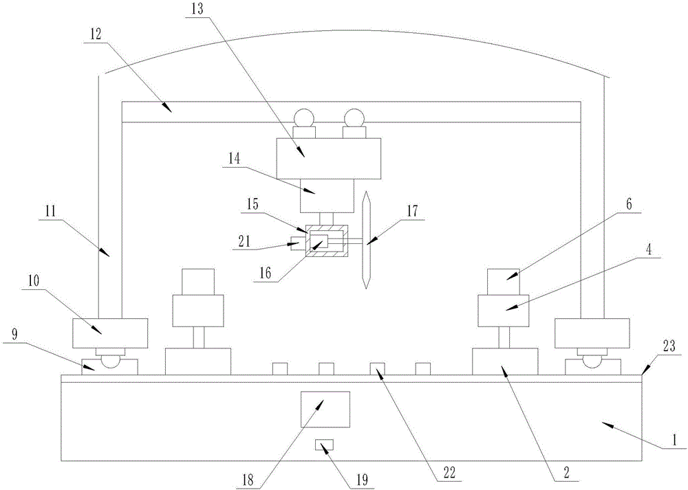
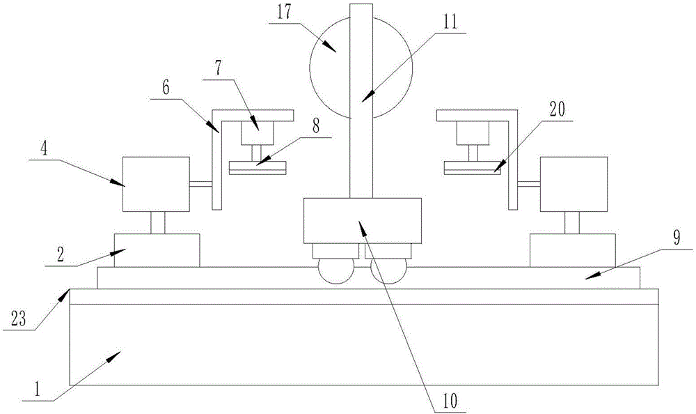
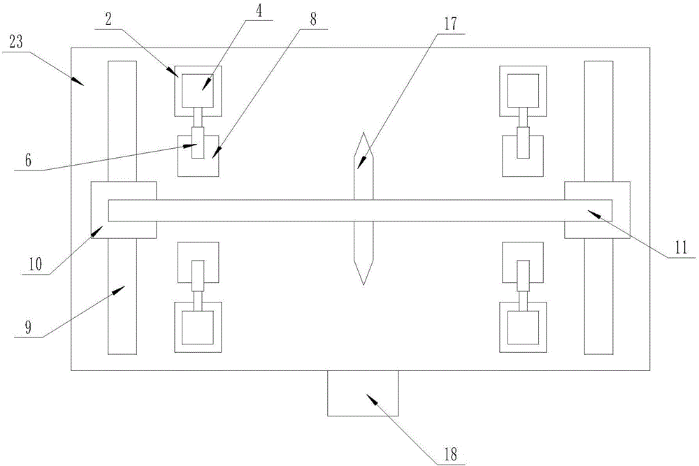
[0016] The present invention is specifically described below in conjunction with accompanying drawing, as Figure 1-4 As shown, a steel bar cutting process includes a workbench (1), and the upper surface of the workbench (1) is provided with a clamping mechanism, and the clamping mechanism is installed by two groups arranged on the upper surface of the workbench (1). plate (2), the No. 1 linear motor (3) embedded on each mounting plate (2) with the telescopic end upward, the installation box (4) arranged on the telescopic end of each No. 1 linear motor (3), An electric push rod (5) arranged in each installation box (4) with a telescopic end in a horizontal direction, an L-shaped top plate (6) arranged on one side of each installation box (4), and an L-shaped top plate (6) arranged on each L-shaped top plate (6) The No. 2 linear motor (7) on the lower surface of the crossbeam with the telescopic end facing down and the pressure plate (8) arranged on the telescopic end of each N...


PUM


Abstract

The invention discloses a cutting process for a reinforcing steel bar. The cutting process comprises a worktable, wherein a clamping mechanism is arranged on the upper surface of the worktable; the telescopic end of each electric push rod is fixedly connected with a corresponding L-shaped top plate; sliding rails are arranged on the upper surface of the worktable and are located on two sides of two groups of mounting plates; a first electric trolley is arranged on each sliding rail; a portal frame is jointly connected onto the upper surfaces of all the first electric trolleys; a controller is arranged on the surface of one side of the worktable; a commercial power interface is formed in the lower part of the controller; a power supply wiring end of the controller is connected with the commercial power interface through a wire; and the input end of the controller is separately connected with first linear motors, the electric push rods, second linear motors, the first electric trolleys, a second electric trolley, a third linear motor and a rotating motor through wires. The cutting process disclosed by the invention has the beneficial effects that infrared positioning is adopted, and the equidistant switching speed is high, so that the working efficiency is improved; and spark sputtering does not need to be worried, so that the body safety of a worker is guaranteed.

Description

technical field [0001] The invention relates to the technical field of steel bar cutting, in particular to a steel bar cutting process. Background technique [0002] With the acceleration of the industrialization process, the improvement of the production efficiency of enterprises, the increase of labor costs and raw material costs, the traditional production methods will produce different shapes of steel bars. In some industrial production, the common steel bars The length cannot meet its requirements, so it needs to be cut. When cutting steel bars, equidistant steel bars cannot be cut out at one time, which wastes materials, takes time and effort, and the splashing of sparks during manual cutting will burn the bare skin of the staff. Potential safety hazards, the existing steel bar cutting device has high maintenance costs and is not suitable for some small and medium-sized enterprises. In order to meet market demand, better and more complete equipment is needed for steel ...

Claims


Application Information

Patent Timeline
Patent Type & Authority Applications(China)
IPC IPC(8): B21F11/00
CPCB21F11/00
Inventor 封红雨
Owner QINGDAO RUBBER VALLEY INTPROP CO LTD
Learn More