
Underwater welding device and method for resistance welding

An underwater welding and resistance welding technology, applied in resistance welding equipment, welding equipment, metal processing equipment, etc., can solve the problems of the tip of the parallel electrode welding head being easily oxidized and damaged, damage to the welding electrode, and peeling of the substrate pad.

Inactive Publication Date: 2017-05-10
GUANGZHOU MICRO WELDING EQUIP
View PDF9 Cites 5 Cited by
  • Summary
  • Abstract
  • Description
  • Claims
  • Application Information

AI Technical Summary

Problems solved by technology

Due to the large welding current of resistance welding, the resistance heat generated is very high. When the upper and lower electrodes are used for double-sided spot welding of the workpiece to be welded, it will inevitably cause deformation of the workpiece near the welding point. Continuous rapid welding will also cause overheating of the upper and lower electrodes. The solder joints stick and damage the end face of the welding electrode; when single-sided spot welding is performed with parallel electrodes or parallel electrode welding heads, the base pads of the workpiece to be welded (such as the base pads on the printed circuit) are often fixed with the insulating liner. Connected or inlaid, the resistance heat generated by the parallel electrode welding head and the workpiece to be welded is too high, often causing the substrate pad to peel off
In addition, in the air environment, the tip of the high-temperature parallel electrode welding head is easily oxidized and damaged

Method used


Image

  • Underwater welding device and method for resistance welding

Examples


Embodiment Construction

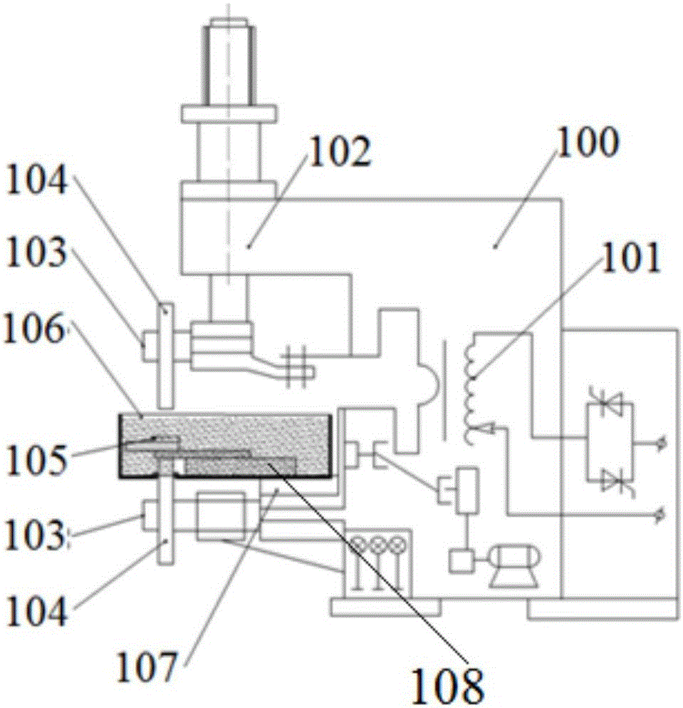
[0017] In order to make the purpose, technical solution and technical effect of the present invention clearer, the present invention will be further described in detail below in conjunction with the accompanying drawings and specific implementation methods. It should be understood that the specific implementations described in this specification are only for explaining the present invention, not for limiting the present invention.

[0018] First of all, it should be noted that the resistance welding underwater welding proposed by the present invention uses resistance welding equipment to weld the welded workpiece submerged in water in the workpiece water tank. For the convenience of description, unless otherwise specified, this manual uses the abbreviation "resistance welding underwater welding".

[0019] As known to those skilled in the art, resistance welding includes two ways of double-sided spot welding and single-sided spot welding, wherein placing two welding electrodes ...


PUM


Abstract

The invention relates to the field of resistance welding and provides underwater welding for resistance welding. Underwater welding for resistance welding refers to welding of a welded workpiece immersed in water in a workpiece water tank by the aid of resistance welding equipment. An underwater welding device for resistance welding comprises the resistance welding equipment, the workpiece water tank, welding electrodes and water; the resistance welding equipment comprises a welding power supply and a spot welding machine head provided with electrode chucks; the welding power supply is electrically connected with the electrode chucks of the spot welding machine head through output cables; welding electrodes are mounted on the electrode chucks; the workpiece water tank is mounted on a working table below the spot welding machine head; and the water is added to the workpiece water tank. Besides, the invention discloses an underwater welding method for resistance welding. Compared with the prior art, the method have the advantages that the underwater welding method for resistance welding is put forward to solve the technical problem of difficulty in heat dissipation of resistance welding in the air environment, resistance welding in the air environment is extended to be underwater welding, and the technical problem about heat dissipation of resistance welding is effectively solved.

Description

technical field [0001] The invention belongs to the field of resistance welding, and more specifically, the invention relates to a resistance welding underwater welding device and a resistance welding underwater welding method. Background technique [0002] At present, resistance welding includes double-side spot welding of upper and lower welding electrodes and single-side spot welding of parallel electrodes or parallel electrode welding heads. The resistance welding of the prior art is performed in an air environment or an inert gas environment. Due to the large welding current of resistance welding, the resistance heat generated is very high. When the upper and lower electrodes are used for double-sided spot welding of the workpiece to be welded, it will inevitably cause deformation of the workpiece near the welding point. Continuous rapid welding will also cause overheating of the upper and lower electrodes. The solder joints stick and damage the end face of the welding ...

Claims


Application Information

Patent Timeline
Patent Type & Authority Applications(China)
IPC IPC(8): B23K11/11B23K11/36
CPCB23K11/115B23K11/36
Inventor 杨仕桐
Owner GUANGZHOU MICRO WELDING EQUIP
Learn More