Numerically-controlled pipe thread lathe adopting laser welding

A technology of laser welding and CNC lathes, which is applied in the field of CNC lathes, can solve problems such as inability to weld, long time, inconvenient automatic operation, etc.

Inactive Publication Date: 2017-05-10
SHANDONG PULUTE MACHINE TOOL
View PDF7 Cites 2 Cited by
  • Summary
  • Abstract
  • Description
  • Claims
  • Application Information

AI Technical Summary

Problems solved by technology

[0002] The pipe thread lathes currently in use can only be used for mechanical cutting of pipes and threads, but cannot be welded; and the welding method currently used can only be welded on site, and cannot directly weld the pipe on the machine tool; and the current electric welding method requires It takes a long time to perform arcing operation, which is not convenient for automatic operation

Method used


Image

  • Numerically-controlled pipe thread lathe adopting laser welding
  • Numerically-controlled pipe thread lathe adopting laser welding

Examples


Embodiment Construction

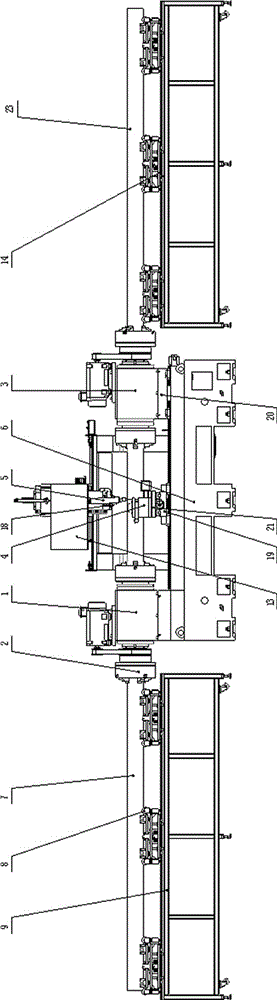
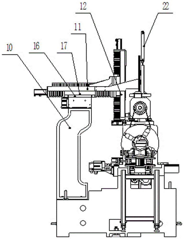
[0018] Specific embodiments of the present invention will be described in detail below in conjunction with the accompanying drawings.

[0019] Such as figure 1 , figure 2 As shown, the fixed headstock 1 is fixedly installed on one end of the bed base 6, a chuck 2 is installed at the front and rear ends of the fixed headstock 1, and the movable headstock 3 is installed on the right end of the bed base 6 along with a sliding seat. 20. The sliding seat 20 is provided with a moving headstock 3, and a chuck is respectively installed at the front and rear ends of the moving headstock 3; the left conveying frame 9 and the right side of the bed base 6 are respectively provided with The right conveyor frame 14; the left conveyor frame 9 and the right conveyor frame 14 are provided with rollers 8; the fixed headstock 1 and the mobile spindle box 3 are clamped by the respective front and rear chucks and sent by the left conveyor frame 9 and the right conveyor frame 14 The left steel p...


PUM


Abstract

The invention discloses a numerically-controlled pipe thread lathe adopting laser welding. The numerically-controlled pipe thread lathe adopting laser welding is composed of two parts, that is, a double-spindle pipe thread lathe and a laser welding platform, wherein during the working of the numerically-controlled pipe thread lathe adopting laser welding, a tool rest is capable of moving in the longitudinal direction or the transversal direction of a rolling guide rail of a machine tool to carry out machining; a laser welding head is capable of moving in the horizontally longitudinal and transversal directions and the vertical direction of the laser welding platform to carry out welding machining on a steel pipe; and different tools can be installed on a turret head and are capable of making transfer movement along the axis of the turret head, and the three-dimensional movement of the tools can also be realized through the movement of a longitudinal guide plate, a transversal guide plate and a vertical guide plate, thus machining such as milling, drilling, tapping and the like are carried out on a workpiece.

Description

technical field [0001] The invention belongs to a numerically controlled lathe, in particular to a numerically controlled lathe for laser welding pipe threads. Background technique [0002] The pipe thread lathes currently in use can only be used for mechanical cutting of pipes and threads, but cannot be welded; and the welding method currently used can only be welded on site, and cannot directly weld the pipe on the machine tool; and the current electric welding method requires It takes a long time to perform the arcing operation, which is not convenient for automatic operation. Contents of the invention [0003] Aiming at the deficiencies of the above-mentioned prior art, the present invention provides a laser welding pipe thread CNC lathe, which combines pipe thread mechanical cutting and laser welding, and integrates turning, milling, drilling, tapping, welding, etc. CNC lathes. [0004] Technical scheme of the present invention is: [0005] A laser welding pipe thr...

Claims


Application Information

Patent Timeline
Patent Type & Authority Applications(China)
IPC IPC(8): B23P23/04
CPCB23P23/04
Inventor 耿建国李兴勇耿明明张令平
Owner SHANDONG PULUTE MACHINE TOOL
Why Eureka
Try Eureka