Copper electroplating groove inlet section and outlet section water blocking buffer apparatus

A buffer device and electroplating copper technology, applied in the electrolysis process, electrolytic components, etc., can solve the problems of damage to the electroplating substrate, failure to ensure that the water retaining device transmission mechanism is synchronized, and there is no water retaining device, etc., to achieve the effect of ensuring quality

Active Publication Date: 2017-05-10
KUN SHAN KORBE PRECISION EQUIP CO LTD
View PDF8 Cites 5 Cited by
  • Summary
  • Abstract
  • Description
  • Claims
  • Application Information

AI Technical Summary

Problems solved by technology

[0002] In continuous electroplating equipment, especially in the inlet and outlet section of the electroplating copper tank, since the notch of the copper tank is usually open, the water flow in the inlet and outlet section is too large, which can easily cause the plated substrate to be stuck or deformed. Wrinkles and other phenomena, in order to improve this situation, a water retaining device is usually installed at the entrance and exit of the copper tank. However, the traditional water retaining device has the following defects: First, the water retaining device does not have a water retaining buffer box. The rubber water-retaining wheel retains water. This kind of device has poor water-retaining effect. Due to the large water flow, it is still impossible to avoid the electroplating substrate being impacted by the water flow after it comes out of the rubber water-retaining wheel, causing the phenomenon of jamming or wrinkling; second, the water retaining The device is not synchronized with the main drive, and a separate motor drive is added, which not only increases the manufacturing cost, but also cannot ensure that the transmission mechanism on the water retaining device is synchronized with the main drive, which can easily cause damage to the electroplating substrate

Method used


Image

  • Copper electroplating groove inlet section and outlet section water blocking buffer apparatus
  • Copper electroplating groove inlet section and outlet section water blocking buffer apparatus

Examples


Embodiment Construction

[0022] The present invention will be described in further detail below in conjunction with the accompanying drawings.

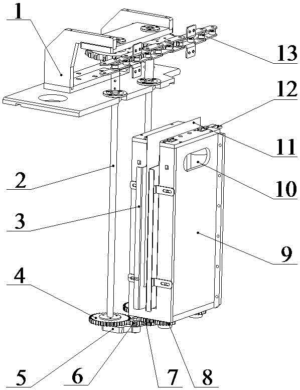
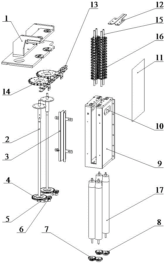
[0023] refer to figure 1 with figure 2 , a water retaining and buffering device for the import and export section of an electroplating copper tank, comprising a main transmission chain 13, a slave conveying device and a water retaining and buffering device, the slave conveying device comprising a fixed seat 1 on the slave transmission wheel, and a lower mount on the slave conveying wheel 5. From the transmission wheel shaft 2, the first from the transmission wheel 14, the second from the transmission wheel 4 and the third from the transmission wheel 6, the transmission wheel shaft 2 is arranged between the upper and lower fixed seats of the transmission wheel, and the first from the transmission wheel The transmission wheel 14 is rotatably connected to the upper end of the slave transmission wheel shaft 2, the second slave transmission wheel 4 is rotatably ...


PUM


Abstract

The present invention relates to the technical field of electroplating equipment, more particularly to a copper electroplating groove inlet section and outlet section water blocking buffer apparatus, which comprises a main conveying chain, a sub-conveying device and a water blocking buffer device, wherein the sub-conveying device comprises a sub-conveying wheel upper fixation seat, a sub-conveying wheel lower fixation seat, a sub-conveying wheel shaft, a first sub-conveying wheel, a second sub-conveying wheel and a third sub-conveying wheel, the sub-conveying wheel shaft is arranged between the sub-conveying wheel upper fixation seat and the sub-conveying wheel lower fixation seat, the first sub-conveying wheel is rotatably connected to the upper end of the sub-conveying wheel shaft, and the second sub-conveying wheel is rotatably connected to the lower end of the sub-conveying wheel shaft. According to the present invention, with the copper electroplating groove inlet section and outlet section water blocking buffer apparatus, it is ensured that the liquid level in the copper groove is maintained at a certain height, such that the liquid in the copper groove maintains the stable and low water flow pressure and the water flow rate, and the phenomenon that the liquid impact causes the plate snapping and the wrinkling of the electroplating substrate cannot be generated when the electroplating substrate enters the copper electroplating groove inlet section and outlet section water blocking buffer apparatus so as to ensure the product quality.

Description

technical field [0001] The invention relates to the technical field of electroplating equipment, in particular to a water retaining and buffering device for an inlet and outlet section of an electroplating copper tank. Background technique [0002] In continuous electroplating equipment, especially in the inlet and outlet section of the electroplating copper tank, since the notch of the copper tank is usually open, the water flow in the inlet and outlet section is too large, which can easily cause the plated substrate to be jammed or deformed. Wrinkles and other phenomena, in order to improve this situation, a water retaining device is usually installed at the entrance and exit of the copper tank. However, the traditional water retaining device has the following defects: First, the water retaining device does not have a water retaining buffer box. The rubber water-retaining wheel retains water. This kind of device has poor water-retaining effect. Due to the large water flow,...

Claims


Application Information

Patent Timeline
Patent Type & Authority Applications(China)
IPC IPC(8): C25D17/00
Inventor 王万生
Owner KUN SHAN KORBE PRECISION EQUIP CO LTD
Why Eureka
Try Eureka