

Detection device for angular position of rotating shaft of speed reducer of electric lock and electric lock
A technology for detection devices and electric locks, which is applied to non-mechanical transmission-operated locks, building locks, buildings, etc., can solve the problems of high power consumption, long rotation time of the reduction box, and inability to relatively accurately locate the angular position, etc., to improve the accuracy Accuracy and sensitivity, the effect of avoiding idling
- Summary
- Abstract
- Description
- Claims
- Application Information
AI Technical Summary
Problems solved by technology
Method used
Image

Examples
Embodiment 1
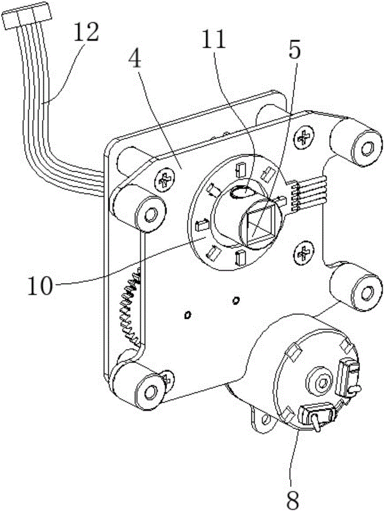
[0031] This embodiment has made a detailed introduction to the angular position detection device of the electric lock reducer box, refer to figure 2 , image 3 As shown, a Hall switch assembly 10 is arranged on the rotating shaft 5 of the gear reducer box 4 of the lock. In the Hall switch assembly 10, several Hall switches are evenly distributed around the rotating shaft 5. The rotating shaft 5 is provided with a permanent magnet 11 to sense the Hall switch. , comparing the output currents of the Hall switches to determine which Hall switch the permanent magnet 11 is close to, thereby detecting the rotation angle of the rotating shaft 5 .
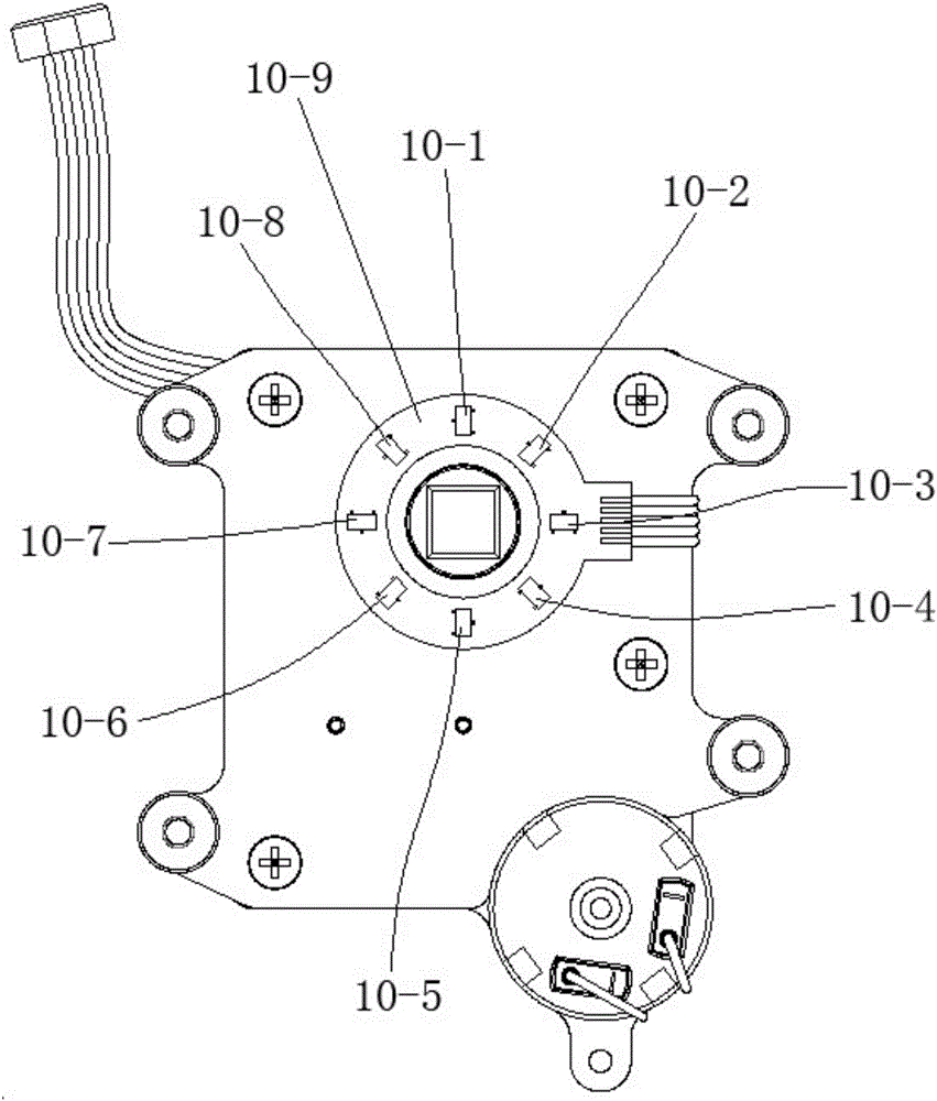
[0032] The Hall switch assembly 10 includes a ring-shaped PCB 10-9, and several Hall switches are evenly distributed on the ring-shaped PCB 10-9. Wires 12 are connected to the PCB 10-9.
[0033] The annular PCB10-9 is fixed on the vertical plate inside the reduction box, and the rotating shaft 5 passes through the central hole of the ann...
Embodiment 2
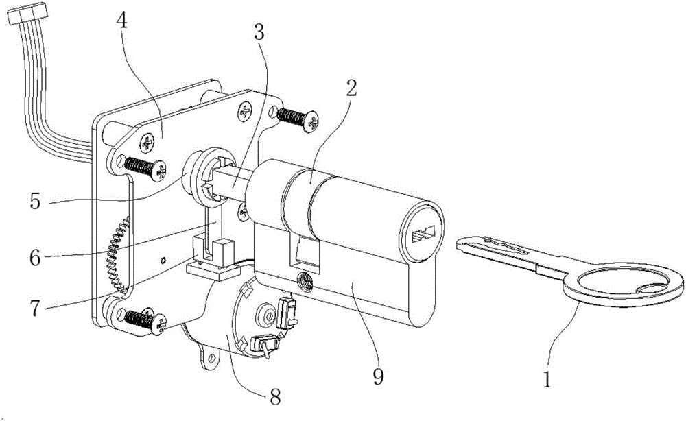
[0042] This embodiment has done a detailed introduction to the electric lock, refer to figure 2 , image 3 As shown, a lock body (not shown in the figure), a lock cylinder (refer to figure 1 Lock core 9) in, motor 8 and reduction box 4, reduction box 4 is provided with rotating shaft 5 and is connected with lock core, is also provided with electric lock reduction box rotating shaft angular position detection device described in embodiment 1.
[0043] There is a dial 2 on the lock cylinder, refer to figure 1 As shown, the rotating shaft 5 drives the dial 2 to rotate so as to open the lock body or close the lock body.
[0044] The working principle of the lock cylinder used in this embodiment can refer to the door locks in the prior art, such as traditional door locks or electronic locks.
[0045] The rotating shaft 5 is provided with a rectangular hole in the axial direction, and the lock cylinder is provided with a transmission shaft with a rectangular cross section connec...
PUM
 Abstract
Description
Claims
Application Information