
A rotary drilling tool

A technology of rotary punching drilling and assembly, applied in the field of rotary punching drilling tools, can solve the problems that the service life cannot meet the requirements of on-site use, and the internal structure, materials and process technology of the drilling tools cannot be seen, so as to prevent the accident of falling well. , The effect of compact structure and simple structure

Inactive Publication Date: 2018-09-04
成都海猛石油机械有限公司
View PDF6 Cites 0 Cited by
  • Summary
  • Abstract
  • Description
  • Claims
  • Application Information

AI Technical Summary

Problems solved by technology

[0002] At present, in domestic and foreign drilling construction operations, the relevant rotary and impact combined rock breaking technology has been verified. At present, only a small number of similar tools of large foreign companies have been successfully used in batches, but foreign companies have done a good job of keeping secrets. We It is impossible to see the internal structure of the drilling tool, and it can only be guessed from the appearance and functional description that its structural principle is the built-in impact generator in the transmission shaft of the oil-sealed screw drilling tool
The structure of each company may be slightly different, and some domestic companies and research institutions are doing related research, either staying in theoretical research, or some related materials and technology are immature, and the service life cannot meet the requirements of field use, so there has not been any Bulk promotion and use

Method used


Image

  • A rotary drilling tool
  • A rotary drilling tool
  • A rotary drilling tool

Examples


Embodiment Construction

[0038] The technical solution of the present invention will be further described below in conjunction with the accompanying drawings.

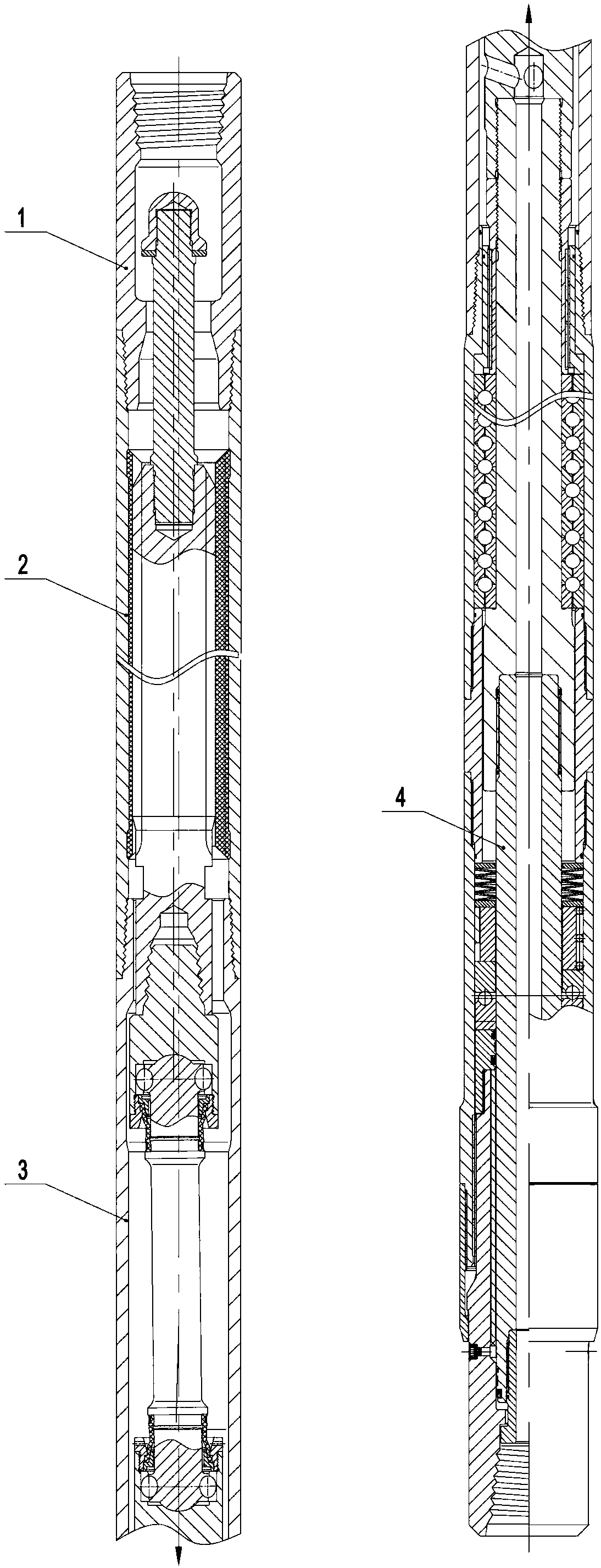
[0039] Such as figure 1 As shown, a rotary percussion drilling tool includes an anti-drop conversion assembly 1, a motor assembly 2, a cardan shaft assembly 3 and a transmission impact assembly 4;

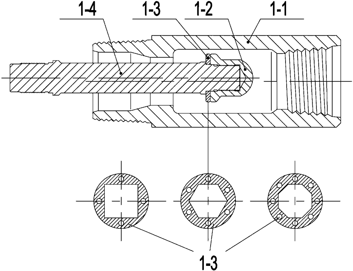
[0040] Such as figure 2 As shown, the anti-drop conversion assembly 1 includes an anti-drop conversion joint 1-1, an anti-drop disc 1-3 and an anti-drop connecting rod 1-4, and an anti-drop conversion joint 1-1 is provided with an anti-drop disc 1- 3. The upper end of the anti-drop connecting rod 1-4 is inserted into the anti-drop disc 1-3, and fixed by the backup nut 1-2, and the other end of the anti-drop connecting rod 1-4 is connected to the rotor 2-2 of the motor assembly 2 upper end;

[0041] The upper end of the anti-drop conversion joint 1-1 is connected to the drill string, and the lower end of the anti-drop connecting rod 1-4 is conne...


PUM


Abstract

The invention discloses a novel rotary percussion drilling tool. The tool comprises an anti-dropping switching assembly, a motor assembly, a universal shaft assembly and a driving impact assembly. The interior of the anti-dropping switching assembly is provided with anti-dropping discs. An anti-dropping connecting rod is fixed by a spare fastening nut. An upper spherical joint and a lower spherical joint of the universal shaft assembly are connected to two ends of a spherically-hinged connecting rod through a movably articulated manner. Driving balls are utilized for transferring torque. The upper spherical joint is connected with a rotor of the motor assembly. The lower spherical joint is connected with a driving shaft of the driving impact assembly. One end of the driving shaft is connected with the lower spherical joint and the other end of the driving shaft is connected with a spline mandrel. The bottom of the spline mandrel stretches into a spline housing. The novel rotary percussion drilling tool has following beneficial effects: an impact generator is arranged in an open-type lubricating driving shaft assembly; the drilling tool is simple in structure; functions of rotary drilling and directional drilling for a bent housing of a common screw drill tool and a turbine drill can be fulfilled; and meanwhile, the function of an impact drill is also fulfilled so that drilling speed is effectively increased.

Description

technical field [0001] The invention belongs to the technical field of drilling, in particular to a rotary percussion drilling tool. Background technique [0002] At present, in domestic and foreign drilling construction operations, the relevant rotary and impact combined rock breaking technology has been verified. At present, only a small number of similar tools of large foreign companies have been successfully used in batches, but foreign companies have done a good job of keeping secrets. We It is impossible to see the internal structure of the drilling tool, and it can only be guessed from the appearance and functional description that its structural principle is the built-in impact generator in the drive shaft of the oil-sealed screw drilling tool. The structure of each company may be slightly different, and some domestic companies and research institutions are doing related research, either staying in theoretical research, or some related materials and technology are im...

Claims


Application Information

Patent Timeline
Patent Type & Authority Patents(China)
IPC IPC(8): E21B6/00
CPCE21B6/00
Inventor 黄瑞海
Owner 成都海猛石油机械有限公司
Learn More