Closed sand mixing device and method

A sand mixing and sand conveying technology, applied in chemical instruments and methods, mixers, earthwork drilling, etc., can solve the problems of large water lock damage, small pore throats, low abundance, etc., to improve sand conveying speed, reduce Seal failure, small footprint effect

Active Publication Date: 2017-05-10
BC P INC CHINA NAT PETROLEUM CORP +1
View PDF17 Cites 14 Cited by
  • Summary
  • Abstract
  • Description
  • Claims
  • Application Information

AI Technical Summary

Problems solved by technology

[0002]Low-permeability oil and gas reservoirs have the characteristics of low porosity, low permeability, low abundance, small pore throats, and strong water lock damage. Currently, the water-based fracturing fluid used is large Large-scale hydraulic fracturing technology has great water lock damage and difficult flowback

Method used


Image

  • Closed sand mixing device and method

Examples


Embodiment 1

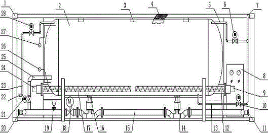
[0025] This embodiment provides a closed sand mixing device, including a frame 1, a tank body 2 arranged in the frame 1 and a main manifold 15 arranged below the tank body 2, the tank body 2 is a horizontal pressure tank, and the The top of the tank body 2 is provided with a gas phase channel, the top is provided with a plurality of sand filling ports 3, the bottom is provided with a liquid phase channel, and the bottom is provided with a plurality of sand outlets. Sand device, the sand outlet is in one-to-one correspondence with the sand delivery device, one end of the sand outlet is connected to the outlet of the sand delivery device, and the other end is connected to the main manifold 15, and the sand delivery device is connected to an electric control cabinet 8. The upper part of the tank body 2 is provided with a gas phase discharge manifold 5, and the gas phase discharge manifold 5 is provided with a gas phase discharge valve 6.

[0026] The airtight sand mixing device i...

Embodiment 2

[0028] On the basis of Embodiment 1, this embodiment provides a closed sand mixing device. The liquid inlet 20 of the main manifold 15 is sequentially provided with a liquid replenishing manifold 25, a flow meter 19 and a differential pressure valve 18 along the direction of liquid flow. , the liquid replenishment manifold 25 communicates with the middle of the tank body 2, and the liquid replenishment manifold 25 is provided with a liquid replenishment valve 21, and the flow meter 19 and the liquid replenishment manifold 25 are both electrically connected to the electric control cabinet 8.

[0029] In this embodiment, the sand conveying device is a sand conveying screw, and the sand conveying screw includes a screw shaft and a motor. The optical axis between the helical part and the helical part in the opposite direction is aligned with the sand outlet, and the motor is electrically connected with the electric control cabinet 8 .

[0030] The sand conveying screw is driven by...

Embodiment 3

[0032] On the basis of Embodiment 2, this embodiment provides a closed sand mixing device, the upper part of the tank body 2 is provided with a nitrogen booster manifold 23, and the nitrogen booster manifold 23 is provided with a nitrogen booster valve 28. The bottom of the tank body 2 is provided with a liquid-phase discharge manifold 13, and the liquid-phase discharge manifold 13 is provided with a liquid-phase discharge valve 10, and the nitrogen booster valve 28 and the liquid-phase discharge valve 10 are all connected Cabinet 8 is electrically connected.

[0033] Among them, the nitrogen pressurization manifold 23 can realize liquid level control during the construction process, replace the liquid in the tank body 2 after the construction is completed, and discharge all the liquid to prevent dry ice from forming in the tank body 2 .

[0034] In this embodiment, the gas phase discharge manifold 5 , the nitrogen pressurization manifold 23 , the liquid phase discharge manifo...


PUM


Abstract

The invention provides a closed sand mixing device. The closed sand mixing device comprises a frame, a tank body arranged in the frame and a main pipe assembly arranged below the tank body. The tank body is a horizontal pressure tank, a gas phase channel is formed in the top of the tank body, a plurality of sand filling ports are formed in the top, a liquid phase channel is formed in the bottom, a plurality of sand outlets are formed in the bottom, a plurality of sand conveying devices are arranged on the inner bottom surface in the tank body, the sand outlets and the sand conveying devices are in one-to-one correspondence, one ends of the sand outlets communicate with outlets of the sand conveying devices while the other ends of the sand outlets communicate with the main pipe assembly, the sand conveying devices are connected to an electric control cabinet, a gas phase discharge pipe assembly is arranged on the upper portion of the tank body, and a gas phase discharge valve is arranged on the gas phase discharge pipe assembly. Liquid carbon dioxide or other liquefied gas and a supporting agent are mixed in a certain proportion and are output in a closed condition under pressure, thereby providing a sand mixing liquid with a certain sand ratio for a fracturing truck.

Description

technical field [0001] The invention belongs to the technical field of downhole fracturing, and in particular relates to a closed sand mixing device and method. Background technique [0002] Low-permeability oil and gas reservoirs have the characteristics of low porosity, low permeability, low abundance, small pore throats, and strong water lock damage. The water-based fracturing fluid large-scale hydraulic fracturing technology currently used has large water lock damage and difficult flowback . Carbon dioxide dry sand fracturing technology, as a kind of waterless fracturing technology, has good applicability to low-permeability and low-pressure oil and gas reservoirs. This technology can realize "waterless fracturing", eliminate reservoir water sensitivity and water lock damage, and improve the effect of fracturing stimulation; the fracturing fluid has no residue, which can protect the reservoir and support fractures; realize independent and rapid flowback. It can greatly...

Claims


Application Information

Patent Timeline
Patent Type & Authority Applications(China)
IPC IPC(8): E21B43/267B01F15/02B01F5/00
CPCE21B43/267B01F2025/9191B01F2025/919125B01F25/00B01F35/712B01F35/75B01F35/75455B01F2101/49Y02P90/70
Inventor 杨延增宋振云温哲豪章东哲叶文勇白建文李前春聂俊王玉李志航苏伟东魏小房方晓军段成才曲先伟
Owner BC P INC CHINA NAT PETROLEUM CORP
Why Eureka
Try Eureka