Supporting structure for six-pilot-holes large-section metro station undercrossing existing line

A technology for subway stations and supporting structures, applied in underground chambers, shaft linings, tunnel linings, etc., can solve the problems of low pile formation efficiency of large-diameter pile foundations, poor overall use function of stations, and large deformation and settlement of existing lines. Achieve the effect of improving the overall use function and riding experience, fast construction speed, and overcoming the difficulty of hole forming

Active Publication Date: 2017-05-10
CHINA RAILWAY LIUYUAN GRP CO LTD
View PDF9 Cites 23 Cited by
  • Summary
  • Abstract
  • Description
  • Claims
  • Application Information

AI Technical Summary

Problems solved by technology

In order to reduce the risk of excavation, the traditional concept of underground excavation under the existing line is generally in the form of a double-hole single-layer with a small cross-section. Poor, the passenger experience is poor, and there are many changes in the excavation process, the deformation and settlement of the existing line is too large, and the space utilization rate is low.
In addition, s

Method used


Image

  • Supporting structure for six-pilot-holes large-section metro station undercrossing existing line
  • Supporting structure for six-pilot-holes large-section metro station undercrossing existing line
  • Supporting structure for six-pilot-holes large-section metro station undercrossing existing line

Examples


Embodiment Construction

[0035] The present invention will be further explained below in conjunction with the drawings.

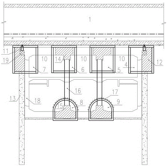
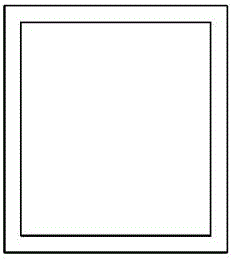
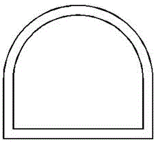
[0036] See as Figure 1-Figure 6 as well as Figure 7-1 to Figure 7-12 As shown, the technical scheme adopted in this specific embodiment is: it includes working well 2, advanced soil reinforcement 3, No. 1 pilot hole 4, No. 2 pilot hole 5, No. 3 pilot hole 6, No. 4 pilot hole 7, 5 No. 8 pilot hole, No. 6 pilot hole 9, the soil between the upper pilot hole 10, the jack 11, the pile crown beam 12, the bored pile 13, the top longitudinal beam and part of the roof 14, the bottom longitudinal beam and part of the bottom plate 15 , Steel pipe column 16, advance conduit 17, underpass station main structure 18, jack temporary support mechanism 19, steel plate 20, pilot tunnel initial support 21, crown beam top embedded grouting conduit 22; two working wells 2 are arranged symmetrically On the left and right sides of the existing line 1, and between the two working wells 2, there is advanced...


PUM


Abstract

Provided is a supporting structure for a six-pilot-holes large-section metro station undercrossing existing line. The invention relates to the field of tunnel and underground engineering construction; two operation wells are symmetrically arranged at the right side and the left side of the existing line, and an advanced reinforcement soil is arranged between the two operation wells and at the lower portion of the existing line, two layers of guiding holes are arranged in the advanced reinforcement soil, the upper guiding holes from left to right are a fourth guiding hole, a third guiding hole, a second guiding hole, a first guiding hole; a fifth guiding hole and a sixth guiding hole are arranged under the third guiding hole and the second guiding hole respectively; beams at pile top are arranged in the first guiding hole and the fourth guiding hole, a lifting jack temporary support mechanism is arranged at a stair part of the upper portion of the beams at the pile top, a lifting jack is arranged at the upper portion of the lifting jack temporary support mechanism, a steel plate is arranged at the upper portion of the lifting jack. The supporting structure can not only control the settlement of the existing line remarkably, which ensures safety operation of the existing line, but also can achieve communication between metro station hall and platform floor, which remarkably improves overall use function and the riding experience of the station.

Description

Technical field [0001] The invention relates to the field of tunnel and underground engineering construction, in particular to a supporting structure for a six-guide tunnel large-section subway station underneath an existing line. Background technique [0002] my country is in a period of large-scale underground space development with large-scale urban subway construction as the main body. More and more intersections of subway lines need to cross existing lines. Undercutting underneath the existing line is one of the most difficult and risky key projects in the subway construction process. The traditional underground excavation method of underground excavation under the existing line often adopts the multi-guide tunnel CRD method, the double-side tunnel method, the PBA method and the hole column method, etc. The arches generally adopt the arc roof form, and the new line and the existing line Interlayer soil is left between the lines to facilitate grouting and reinforcement. Th...

Claims


Application Information

Patent Timeline
IPC IPC(8): E21D11/00E21D11/10E21D9/14
CPCE21D9/14E21D11/00E21D11/10Y02E10/20
Inventor 李利柏林赵晋友贺维国张美琴任玉瑾孙俊利吴琼杨超峰石广银
Owner CHINA RAILWAY LIUYUAN GRP CO LTD
Why Eureka
Try Eureka