
Separated type compressor

A compressor and split-type technology, applied in the field of compressors, can solve problems such as unfavorable compressor maintenance, and achieve the effect of convenient disassembly

Inactive Publication Date: 2017-05-10
TAIZHOU GREEN ELECTRIC APPLIANCE MFG
View PDF6 Cites 1 Cited by
  • Summary
  • Abstract
  • Description
  • Claims
  • Application Information

AI Technical Summary

Problems solved by technology

At present, the motor and compression cylinder of compressors widely used are mostly integrated structures, which are not conducive to the later maintenance of compressors.

Method used


Image

  • Separated type compressor

Examples


Embodiment Construction

[0011] The preferred embodiments of the present invention will be described in detail below in conjunction with the accompanying drawings, so that the advantages and features of the present invention can be more easily understood by those skilled in the art, so as to define the protection scope of the present invention more clearly.

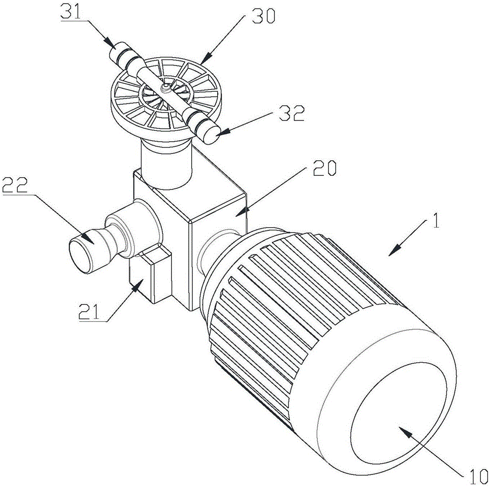
[0012] like figure 1 As shown, a split compressor 1 includes a drive motor 10 and a compression cylinder 20, the drive motor 10 and the compression cylinder 20 are independent of each other, the drive motor 10 drives the compression cylinder 20 to compress gas, and the compression cylinder 20 is provided with a cooler 21, the side of the compression cylinder 20 is provided with an air inlet 22, the top of the compression cylinder 20 is provided with a turntable 30, the turntable 30 is provided with a first air outlet 31 and a second air outlet 32, the first air outlet 31, the second The air outlets 32 communicate with the compression cylinders 20...


PUM


Abstract

The invention discloses a separated type compressor. The separated type compressor comprises a driving motor and a compression air cylinder, wherein the driving motor and the compression air cylinder are independent to each other; the driving motor drives the compression air cylinder to compress air and the compression air cylinder is provided with a cooler; an air inlet is formed in one side face of the compression air cylinder; a rotary table is arranged at the top of the compression air cylinder; the rotary table is provided with a first air outlet and a second air outlet; the first air outlet and the second air outlet are communicated with the compression air cylinder respectively; and when the rotary table is rotated, directions of the first air outlet and the second air outlet can be changed. According to the separated type compressor disclosed by the invention, the motor and the air cylinder adopt a mutual independent separated type design and the motor and the air cylinder are easily separated; and the maintenance and the detachment in a later period are convenient. The air outlet of the compressor is designed into a double-channel rotary table type structure, and the direction of the air outlet can be flexibly changed, so that the air outlet is conveniently connected with an external connector; and the separated type compressor is more flexible and convenient to use.

Description

technical field [0001] The invention relates to a compressor, more precisely, a split compressor. Background technique [0002] The compressor is a driven fluid machine that lifts low-pressure gas into high-pressure gas, and is the heart of the refrigeration system. It inhales low-temperature and low-pressure refrigerant gas from the suction pipe, drives the piston to compress it through the operation of the motor, and discharges high-temperature and high-pressure refrigerant gas to the exhaust pipe to provide power for the refrigeration cycle, thereby realizing compression → condensation (heat release )→expansion→evaporation (endothermic) refrigeration cycle. At present, the motor and compression cylinder of compressors widely used are mostly integrated structures, which are not conducive to the later maintenance of compressors. Contents of the invention [0003] The present invention mainly solves the technical problems existing in the prior art, thereby providing ...

Claims


Application Information

Patent Timeline
Patent Type & Authority Applications(China)
IPC IPC(8): F04B35/04F04B39/12
CPCF04B35/04F04B39/123
Inventor 龚志清
Owner TAIZHOU GREEN ELECTRIC APPLIANCE MFG
Learn More