A test water gate control device

A control device and test technology, applied in valve device, valve operation/release device, valve details, etc., can solve problems such as poor control accuracy, fluctuating liquid flow, and inability to continuously adjust pipeline liquid flow, etc. To achieve the effect of precise liquid flow and precise adjustment

Inactive Publication Date: 2019-05-21
ANHUI JIANGHUAI AUTOMOBILE GRP CORP LTD
View PDF8 Cites 0 Cited by
  • Summary
  • Abstract
  • Description
  • Claims
  • Application Information

AI Technical Summary

Problems solved by technology

The device has only two states: liquid flow and liquid cut-off, and cannot continuously adjust the liquid flow inside the pipeline, which will lead to poor control accuracy and fluctuating liquid flow

Method used


Image

  • A test water gate control device
  • A test water gate control device

Examples


Embodiment Construction

[0025] Embodiments of the present invention are described in detail below, and examples of the embodiments are shown in the drawings, wherein the same or similar reference numerals denote the same or similar elements or elements having the same or similar functions throughout. The embodiments described below by referring to the figures are exemplary only for explaining the present invention and should not be construed as limiting the present invention.

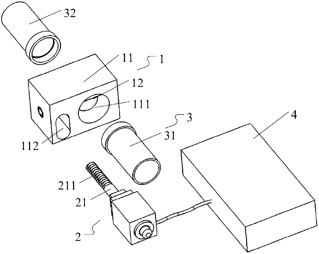
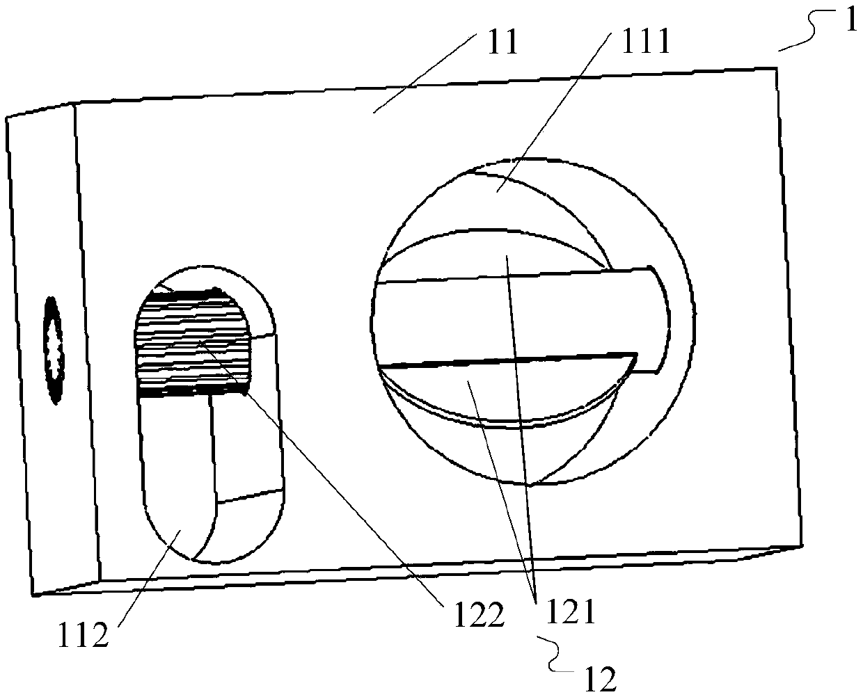
[0026] Such as figure 1 , figure 2 As shown, the embodiment of the present invention provides a test water valve control device, which includes: a valve mechanism 1, a stepper motor 2, a pipeline 3, a flow sensor (not shown) and a control unit 4, and the valve mechanism 1 includes a main body 11 and the adjustment shaft 12, the main body 11 is provided with a flow guide hole 111, the adjustment shaft 12 is arranged in the flow guide hole 111, and the two ends of the adjustment shaft 12 are respectively rotatably matched with...


PUM


Abstract

The invention discloses a water gate control device for tests. The water gate control device comprises a valve mechanism, a stepping motor, a pipeline, a flow sensor and a control unit. The valve mechanism comprises a body and an adjusting shaft, the body is provided with a flow guide through hole, and the adjusting shaft penetrates through the flow guide through hole to be in rotating fit with the body; the adjusting shaft is provided with a valve plate, and the valve plate is matched with the flow guide through hole; the pipeline comprises a water outlet pipe and a water inlet pipe, the water outlet pipe and the water inlet pipe are fixed to the two ends of the flow guide through hole respectively, and the flow sensor is located in the water outlet pipe; the control unit is connected with the stepping motor and the flow sensor. According to the device, the real-time flow value of liquid is acquired through the flow sensor, the control unit compares the real-time flow value of the liquid with a target flow value and outputs a control signal to the stepping motor, the stepping motor drives the adjusting shaft to drive the valve plate to rotate, the opening degree of the flow guide through hole can be flexibly adjusted, and the flow of the liquid can be adjusted more stably and more precisely.

Description

technical field [0001] The invention relates to a test water gate control device. Background technique [0002] Existing mechanical equipment often contains liquid pipelines, and often the liquid flow in these liquid pipelines needs to be adjusted and controlled, for example: a pipeline system for cooling, in order to ensure that the temperature of the cooled medium is not too high or too low , it is necessary to adjust the flow rate of the cold water in the cooling pipeline, and the adjustment accuracy is relatively high. A common device for controlling the flow of cooling water in a liquid pipeline consists of two parts: an electric valve and a valve body; the electric valve can be driven by an electric signal to make a 90° rotation, and the rotation of the electric valve can drive the ball valve or valve in the valve body below. The piece rotates 90°, which realizes the circulation and blocking of the liquid medium in the pipeline. By controlling the outflow or cut-off ...

Claims


Application Information

Patent Timeline
Patent Type & Authority Patents(China)
IPC IPC(8): F16K31/04F16K37/00F16K1/22
CPCF16K1/223F16K31/042F16K37/0091
Inventor 徐明宋长青卜子华谢飞飞徐峰刘家祥
Owner ANHUI JIANGHUAI AUTOMOBILE GRP CORP LTD
Why Eureka
Try Eureka