Force measuring device

A force measuring device and testing shaft technology, applied in measuring devices, force/torque/work measuring instruments, instruments, etc., can solve problems such as lack of effective testing ability for mechanical properties, and achieve simple structure, improved life, and high measurement accuracy. Effect

Active Publication Date: 2017-05-10
CHINA PETROCHEMICAL CORP +4
View PDF8 Cites 1 Cited by
  • Summary
  • Abstract
  • Description
  • Claims
  • Application Information

AI Technical Summary

Problems solved by technology

Existing tools lack effective testing capabilities for the mechanical properties of components in such liquid-flowing environments

Method used


Image

  • Force measuring device
  • Force measuring device

Examples


Embodiment example 1

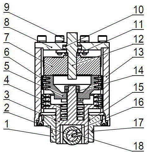
[0022] as attached figure 1 As shown, the force measuring device includes a guide sleeve 1 , a test shaft 3 , a mounting plate 5 , a sensor 7 , a cover 8 and a bracket 13 . The sensor 7 is connected to the test shaft 3 through the mounting plate 5; the test shaft 3 is installed in the guide sleeve 1, and one end of the guide sleeve 1 and the bracket 13 is fixedly connected by a bolt; The contact part of the cover 8 and the adjustment rod 12 is equipped with a bearing 10. The bearing 10 and the adjustment rod 12 are fixedly installed on the cover 8 through the small cover plate 11. The adjustment rod 12 passes through the sensor 7 and forms a spiral fit with the sensor 7. Rotating the adjusting rod 12 can push the sensor 7 to move. A wheel shaft 2 is installed on the test shaft 3 , and a test pressure head 16 is fixedly mounted on the wheel shaft 2 through a pin 18 . Guide rails 6 are fixedly installed on the outer surfaces of the mounting plate 5 and the test shaft 3 respect...

Embodiment example 2

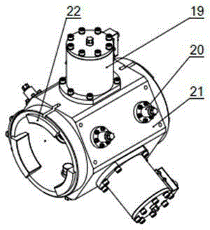
[0026] Refer to attached figure 2 , On the basis of Embodiment 1, the entire force measuring device 19 is fixedly installed on the base 21 . A fastening device 20 and pads 22 are installed on the base 21 .

[0027] In Example 1, different mounting bases can be selected for the force measuring device 19. During the design process, a suitable mounting base can be designed according to the shape of the component to be tested to match the moving component to ensure the accuracy of the testing process. The fastening method of the moving component can be selected according to the shape and structure of the component to be tested. The preferred fastening device can be clamped by the top screw, and the number can be selected as one or more according to the needs; at the same time, it can also be designed according to the needs Pads to ensure good contact between irregularly shaped components and the base, eliminating measurement errors caused by poor contact during the test.

[002...


PUM


Abstract

A force measuring device is disclosed and comprises a guide sleeve, a testing shaft, an installation plate, a sensor, a sealing cover, a support rack and an elastic member, wherein the sensor is connected with the testing shaft via the installation plate, the testing shaft is mounted in the guide sleeve, a wheel shaft is mounted on the testing shaft, and a testing pressure head is fixedly mounted on the wheel shaft. Outer surfaces of the installation plate and the testing shaft are provided with guide rails. An adjusting rod is mounted on the sealing cover; a bearing is mounted on a part, contacting with the adjusting rod, of the sealing cover; the elastic member is mounted on the testing shaft, and one end is in contact with the testing shaft while the other end is in contact with the installation plate; sealing rings are mounted between the testing shaft and the guide sleeve and on an outer surface of the guide sleeve. The measuring device is simple in structure, easy in installation, high in measurement accuracy and great in reliability and practicality; the measuring device can be used for measuring force acting on a stationary or moving member.

Description

technical field [0001] The invention relates to a force-measuring device in the field of mechanical performance testing devices, and is particularly suitable for testing the mechanical properties of components in an environment where liquid flows through. Background technique [0002] The use of mechanical performance testing methods can improve the qualified rate of finished products before leaving the factory and ensure the reliability of products during use. At present, the commonly used method for product mechanical performance testing is to apply force to the elastic member, and measure the stress of the component by measuring the deflection or strain of the elastic member, and then judge the product performance characteristics. In the conventional measurement process, this measurement method can accurately reflect the force on the measured component. However, when the test component rotates, or when the test component performs more complex movements such as linear moti...

Claims


Application Information

Patent Timeline
Patent Type & Authority Applications(China)
IPC IPC(8): G01L5/00
Inventor 王义峰孙峰高丽萍刘文庭陈威张晓林
Owner CHINA PETROCHEMICAL CORP
Why Eureka
Try Eureka