Positioning system and method of spacecraft subjected to space junk collision

A space debris and positioning system technology, applied in instruments, scientific instruments, analyzing solids using sonic/ultrasonic/infrasonic waves, etc., can solve the problem of low positioning accuracy of the system, and achieve the effects of fast response speed, small amount of calculation, and simple operation

Active Publication Date: 2017-05-10
BEIJING INST OF SPACECRAFT SYST ENG
View PDF4 Cites 11 Cited by
  • Summary
  • Abstract
  • Description
  • Claims
  • Application Information

AI Technical Summary

Problems solved by technology

[0004] At present, the sensing and positioning system based on acoustic emission technology mainly senses and locates by collecting the Lamb waves generated by space debris hitting the spacecraft shell structure, but the propagation speed and frequency of the Lamb wave in the spacecraft shell and the thickness of the shell Therefore, under the premise of a certain number of sensors, the positioning accuracy of the system is not high

Method used


Image

  • Positioning system and method of spacecraft subjected to space junk collision
  • Positioning system and method of spacecraft subjected to space junk collision
  • Positioning system and method of spacecraft subjected to space junk collision

Examples


Embodiment Construction

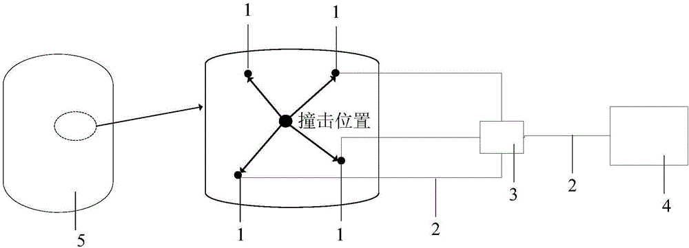
[0023] Such as figure 1 As shown, it is a block diagram of the composition principle of the positioning system of the present invention. The system of the present invention mainly includes an in-plane shear wave piezoelectric sensor 1, a data transmission line 2, a charge amplifier 3 and a data processing unit 4, and 5 in the figure is a spacecraft structure. The in-plane shear wave piezoelectric sensor 1 is fixed on the inner surface of the spacecraft structure 5 by bonding, and a plurality of in-plane shear wave piezoelectric sensors 1 form a sensor array (for example, the distance between any nearest neighbor sensors is less than 2m). The transmission line 2 is connected to the charge amplifier 3 , and the charge amplifier 3 is connected to the data processing unit 4 through the data transmission line 2 .

[0024] The in-plane shear wave piezoelectric sensor 1 is made of piezoelectric ceramic PZT, and the manufacturing method is the same as the literature SmartMater.Struc.2...


PUM


Abstract

The invention provides a positioning system and method of a spacecraft subjected to space junk collision. The positioning system comprises in-plane shearing wave piezoelectric sensors (1), a data transmission line (2), a charge amplifier (3) and a data processing unit (4), wherein the in-plane shearing wave piezoelectric sensors (1) are glued and fixed on an inner surface of a spacecraft structure (5); a sensor array is composed of the plurality of in-plane shearing wave piezoelectric sensors (1) and the in-plane shearing wave piezoelectric sensors (1) are connected with the charge amplifier (3) through the data transmission line (2); and the charge amplifier (3) is connected with the data processing unit (4) through the data transmission line (2). After collision occurs, the data processing unit (4) is used for acquiring data of the in-plane shearing wave piezoelectric sensors (1) in real time, and the positioning system is used for carrying out collision positioning of space junks through in-plane shearing wave SHO (Super High Output) wave and a four-point geometric positioning method, so that high-precision positioning of a collision position can be realized.

Description

technical field [0001] The invention belongs to the field of health monitoring of spacecraft structures, and relates to a positioning system and a positioning method for the outer shell of a spacecraft being impacted by space debris. The in-plane shear wave generated by the impact of space debris on the shell structure of a spacecraft is used to locate the impact position , with high positioning accuracy. Background technique [0002] With the continuous development of human spaceflight activities, the space debris environment continues to deteriorate, which poses a great threat to the safety of long-lived spacecraft in orbit. [0003] The sensing and positioning technologies for spacecraft impacted by space debris mainly include sensing positioning based on acoustic emission technology, sensing positioning based on accelerometers, sensing positioning based on thermal imaging, sensing positioning based on optical fiber sensors, sensing positioning based on resistive films, ...

Claims


Application Information

Patent Timeline
Patent Type & Authority Applications(China)
IPC IPC(8): G01N29/04G01N29/24
CPCG01N29/043G01N29/2437G01N2291/023G01N2291/0289G01N2291/0422G01N2291/106
Inventor 周浩王晓宇孙维张欢刘国青梁东平高峰
Owner BEIJING INST OF SPACECRAFT SYST ENG
Why Eureka
Try Eureka