Supercharge Your Innovation With Domain-Expert AI Agents!

Computer side jet flow cooler

A computer and heat sink technology, which is applied in the field of computer side-mounted jet radiators, can solve the problems of air flow overflow and insufficient efficiency, and achieve the effects of less air flow, improved heat dissipation effect, and high wind speed

Inactive Publication Date: 2017-05-10
重庆优之唯电子科技有限公司
View PDF0 Cites 1 Cited by
  • Summary
  • Abstract
  • Description
  • Claims
  • Application Information

AI Technical Summary

Problems solved by technology

[0002] With the development of the economy and the progress of science and technology, the computer has become an indispensable tool for our life and production. Some people spend a long time with the computer every day. However, the computer is a kind of radiation machine, especially the computer case. It is the main radiation source. In order to reduce the radiation of the chassis, the applicant submitted the application number 2016212360708 on November 18, 2016, entitled "A Conduit Type Forced Convection Bottom-Drain Computer Chassis", which can effectively solve the electromagnetic radiation of the computer chassis , the application adopts bottom air inlet and outlet, the inlet air and outlet air are respectively introduced and exhausted through the duct, the air inlet duct points to the components that need heat dissipation, and provides convective air for cooling, but the airflow in the air inlet duct cannot be fully applied to the parts that need to be dissipated. Part, or only applied to a part of a heat dissipation component, and there is a phenomenon of airflow overflow at the same time, and the efficiency of using the imported airflow to dissipate heat is not sufficient, which still needs to be further solved and improved

Method used


Image

  • Computer side jet flow cooler
  • Computer side jet flow cooler
  • Computer side jet flow cooler

Examples


Embodiment Construction

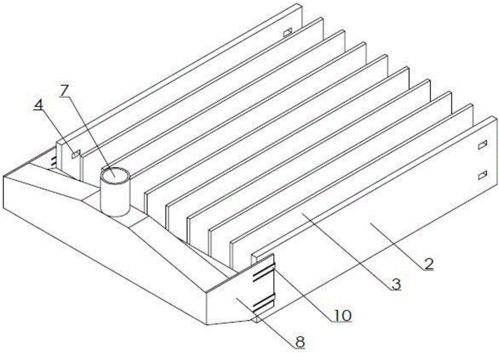
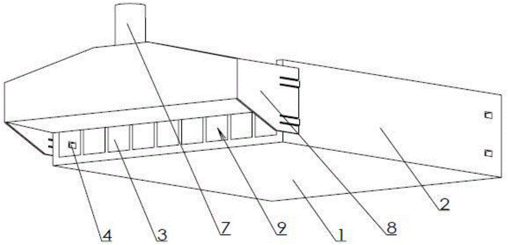
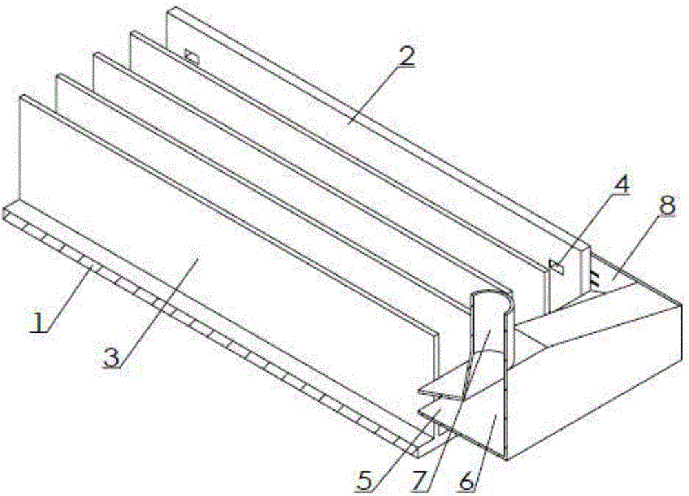
[0014] Examples of the present invention figure 1 , 2 As shown in , 3, the side-mounted jet radiator of the computer is provided with a heat sink and an air guide joint, and the heat sink is provided with a heat dissipation bottom plate 1, and the front of the heat dissipation bottom plate is in contact with the heating component, and the connection method can be screw connection or buckle connection. Parallel longitudinal side plates 2 are respectively connected to both sides of the back of the heat dissipation bottom plate, and a longitudinal wing plate 3 is connected on the back of the heat dissipation bottom plate between the two longitudinal side plates. The longitudinal end of the plate and the longitudinal wing plate are flush, and the two ends of the longitudinal side plate are provided with a bayonet 4; The front view port is in the shape of a long strip, and the section of the strip-shaped air outlet along the airflow direction is trapezoidal, gradually narrowing to...


PUM


Abstract

The invention discloses a computer side jet flow cooler. The jet flow cooler is characterized by comprising cooling fins and an air flow guide connector. The cooling fins are provided with a cooling base plate. The two sides of the back of the cooling base plate are connected with longitudinal side plates which are in parallel with each other. Longitudinal wing plates are connected with the back of the cooling base plate between two adjacent longitudinal side plates. The longitudinal ends of the cooling base plate, longitudinal side plates and the longitudinal wing plates are aligned. Two ends of the longitudinal side plates are provided with buckling holes. The air flow guide connector is provided with a strip air outlet which pushes a longitudinal end at one side of the cooling fins. The strip air outlet is connected with an air inlet buffer cavity. The buffer cavity is connected with an air inlet. Two ends of the strip air outlet are arranged with connection end plates which are pasted to the outer surface of the longitudinal side plate ends. The connection end plates are buckled to the buckling holes through a buckling hook. The strip air outlet keeps a clearance with the cooling base plate. The air flows through the cooling fins in concentration, and the cooling efficiency are higher.

Description

technical field [0001] The invention relates to a heat sink for components inside a computer case, in particular to a side-mounted jet type heat sink for a computer. Background technique [0002] With the development of the economy and the progress of science and technology, the computer has become an indispensable tool for our life and production. Some people spend a long time with the computer every day. However, the computer is a kind of radiation machine, especially the computer case. It is the main radiation source. In order to reduce the radiation of the chassis, the applicant submitted the application number 2016212360708 on November 18, 2016, entitled "A Conduit Type Forced Convection Bottom-Drain Computer Chassis", which can effectively solve the electromagnetic radiation of the computer chassis , the application adopts bottom air inlet and outlet, the inlet air and outlet air are respectively introduced and exhausted through the duct, the air inlet duct points to t...

Claims


Application Information

Patent Timeline
Patent Type & Authority Applications(China)
IPC IPC(8): G06F1/20
CPCG06F1/20
Inventor 王华生
Owner 重庆优之唯电子科技有限公司
Features
  • R&D
  • Intellectual Property
  • Life Sciences
  • Materials
  • Tech Scout
  • Unparalleled Data Quality
  • Higher Quality Content
  • 60% Fewer Hallucinations
Learn More