Supercharge Your Innovation With Domain-Expert AI Agents!

Annular deflector-type radiator for computer

A radiator, computer technology, applied in computing, instrumentation, electrical digital data processing, etc., can solve problems such as insufficient efficiency and airflow

Inactive Publication Date: 2017-05-31
重庆优之唯电子科技有限公司
View PDF0 Cites 0 Cited by
  • Summary
  • Abstract
  • Description
  • Claims
  • Application Information

AI Technical Summary

Problems solved by technology

[0002] With the development of the economy and the progress of science and technology, the computer has become an indispensable tool for our life and production. Some people spend a long time with the computer every day. However, the computer is a kind of radiation machine, especially the computer case. It is the main radiation source. In order to reduce the radiation of the chassis, the applicant submitted the application number 2016212360708 on November 18, 2016, entitled "A Conduit Type Forced Convection Bottom-Drain Computer Chassis", which can effectively solve the electromagnetic radiation of the computer chassis , the application adopts bottom air inlet and outlet, the inlet air and outlet air are respectively introduced and exhausted through the duct, the air inlet duct points to the components that need heat dissipation, and provides convective air for cooling, but the airflow in the air inlet duct cannot be fully applied to the parts that need to be dissipated. Part, or only applied to a part of a heat dissipation component, and there is a phenomenon of airflow overflow at the same time, and the efficiency of using the imported airflow to dissipate heat is not sufficient, which still needs to be further solved and improved

Method used


Image

  • Annular deflector-type radiator for computer
  • Annular deflector-type radiator for computer

Examples


Embodiment Construction

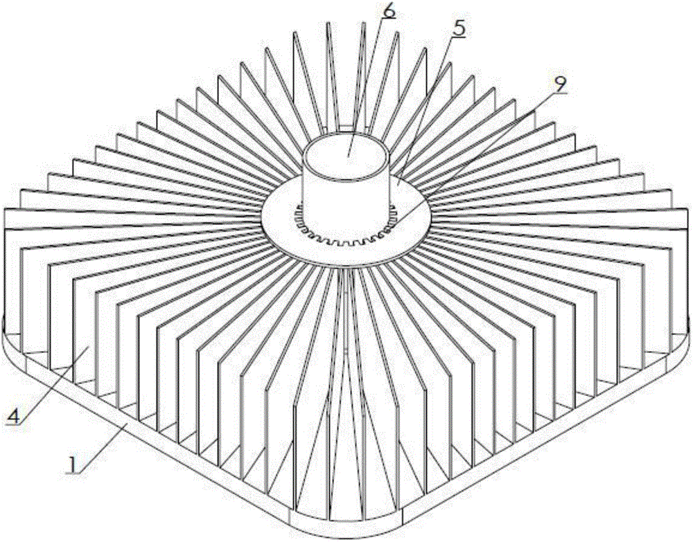
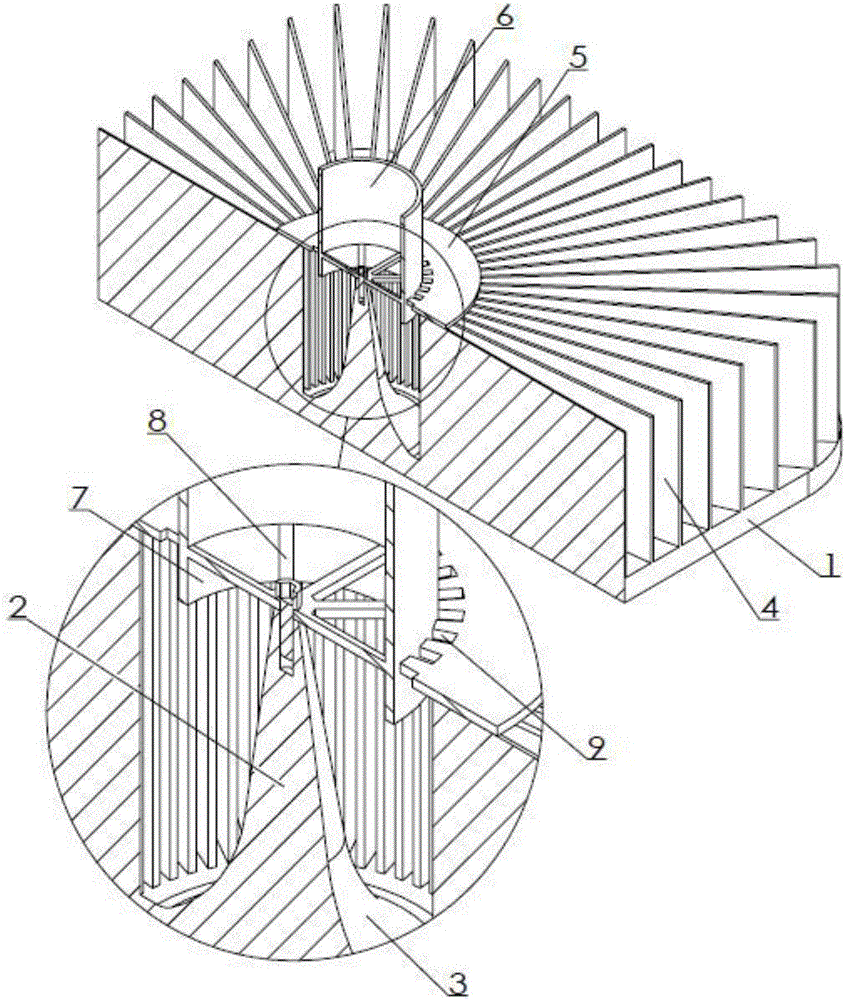
[0011] Examples of the present invention figure 1 , 2 As shown, the computer annular flow guide radiator is provided with heat sinks and air guide joints, the heat sink is provided with a heat dissipation bottom plate 1, and the front of the heat dissipation bottom plate is in contact with the heating components. The connection method can be screw connection or buckle connection, and the shape can be It is circular or polygonal, and this embodiment is a chamfered square, which can be selected according to needs during implementation. A cone 2 is provided at the center of the back of the heat dissipation bottom plate, and the large end of the cone is connected to the back of the heat dissipation bottom plate. The wind flows smoothly and changes direction, and there are radially extending wings 4 distributed around the cone. The inner end of the wing is located outside the curved surface; the air guide joint is provided with an annular pressure piece 5 that is pressed on the inn...


PUM


Abstract

The invention discloses an annular deflector-type radiator for a computer. The radiator is characterized in that a radiating fin and a ventilation joint are included, the radiating fin is provided with a radiating bottom plate, a cone is arranged in the central position of the back of the radiating bottom plate, the large end of the cone is connected with the back of the radiating bottom plate, the connecting position transits through a curved surface, and wing plates extending in the radial direction are distributed in the circumferential direction around the cone; the ventilation joint is provided with an annular pressing sheet which is pressed at the inner ends of the wing plates and is coaxial with the cone, a sleeve which extends to the two sides and is coaxial with the cone is connected to the inner edge of the annular pressing sheet, the outer segment of the sleeve serves as an air inlet connector, the inner segment of the sleeve serves as a guide tube, a radial rib connected with the cone is connected into the sleeve, and drainage holes which are distributed in the circumferential direction are formed in the portion, at the outer side of the sleeve, of the annular pressing sheet. According to the annular deflector-type radiator for the computer, wind flows through the radiating fin more concentratedly, and the radiating efficiency is higher.

Description

technical field [0001] The invention relates to a heat sink for internal parts of a computer case, in particular to a computer annular flow guide type heat sink. Background technique [0002] With the development of the economy and the progress of science and technology, the computer has become an indispensable tool for our life and production. Some people spend a long time with the computer every day. However, the computer is a kind of radiation machine, especially the computer case. It is the main radiation source. In order to reduce the radiation of the chassis, the applicant submitted the application number 2016212360708 on November 18, 2016, entitled "A Conduit Type Forced Convection Bottom-Drain Computer Chassis", which can effectively solve the electromagnetic radiation of the computer chassis , the application adopts bottom air inlet and outlet, the inlet air and outlet air are respectively introduced and exhausted through the duct, the air inlet duct points to the c...

Claims


Application Information

Patent Timeline
IPC IPC(8): G06F1/20
CPCG06F1/20
Inventor 王华生
Owner 重庆优之唯电子科技有限公司
Features
  • R&D
  • Intellectual Property
  • Life Sciences
  • Materials
  • Tech Scout
  • Unparalleled Data Quality
  • Higher Quality Content
  • 60% Fewer Hallucinations
Learn More