Surround shooting method and device, and unmanned aerial vehicle

A surround shooting and drone technology, applied in the field of drones, can solve the problems of difficult shooting of aircraft, complicated operation, weak sense of distance, etc., and achieve the effect of saving user time and simple operation.

Active Publication Date: 2017-05-10
ZEROTECH (SHENZHEN) INTELLIGENCE ROBOT CO LTD
View PDF6 Cites 41 Cited by
  • Summary
  • Abstract
  • Description
  • Claims
  • Application Information

AI Technical Summary

Problems solved by technology

[0002] At present, when the drone is shooting around the target object, the user needs to customize the center position, radius, relative height, etc. For many users, it is difficult for the aircraft to circle the

Method used


Image

  • Surround shooting method and device, and unmanned aerial vehicle
  • Surround shooting method and device, and unmanned aerial vehicle
  • Surround shooting method and device, and unmanned aerial vehicle

Examples


no. 1 example

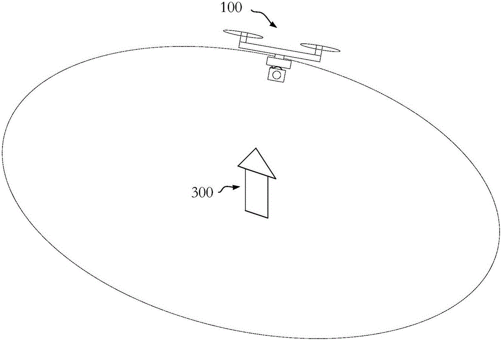
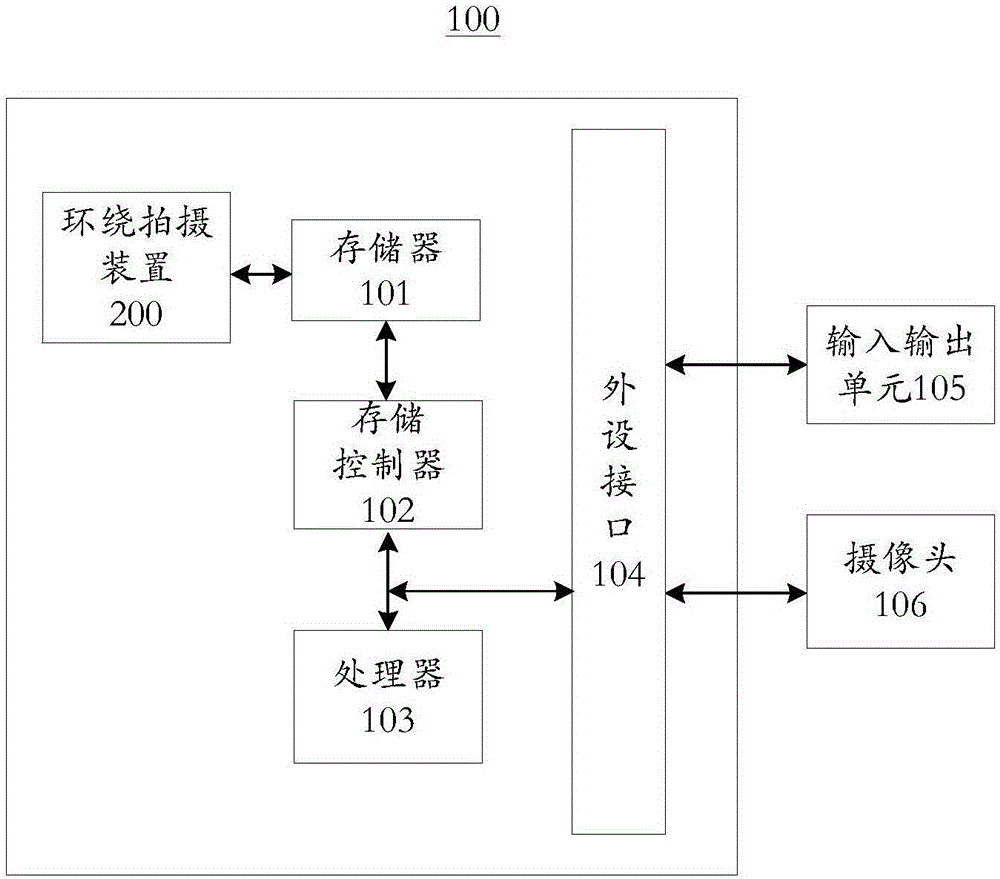
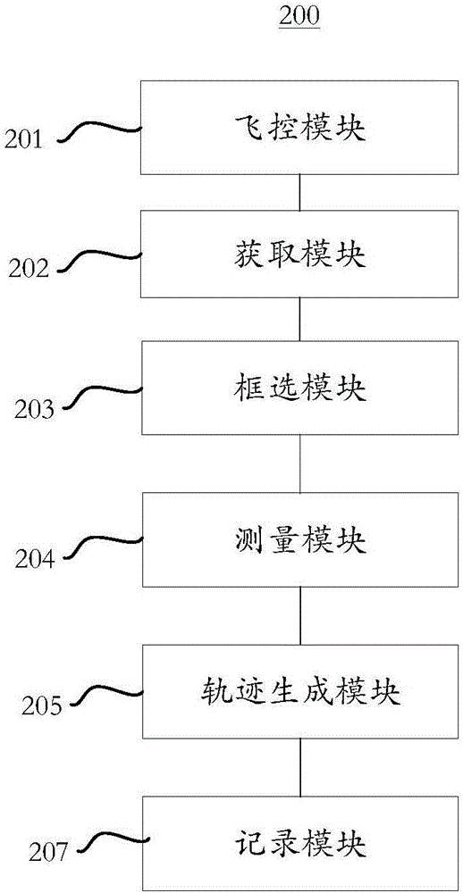
[0028] Please refer to image 3 , is a block diagram of the surrounding shooting device 200 provided in this embodiment, and the surrounding shooting device 200 is applied to the UAV 100 . In this embodiment, the surround shooting device 200 is applied in the first shooting mode. It should be mentioned that in the first shooting mode, the target object 300 is in a static state. The surrounding shooting device 200 includes: an acquisition module 201 , a frame selection module 202 , a flight control module 203 , a calculation module 204 and a trajectory generation module 205 .

[0029] The obtaining module 201 is configured to obtain a preview image captured by the camera 106 at the first position.

[0030] Since the camera 106 captures images in real time, the user can control the drone 100 to fly to any position. Of course, the acquisition module 201 can acquire the image captured by the camera 106 when the drone 100 is at the first position, and use it as a preview image. I...

no. 2 example

[0061] Please refer to Figure 5 , is a block diagram of the surround camera device 200 provided in this embodiment. In this embodiment, the surround shooting device 200 is applied in the second shooting mode. It should be mentioned that in the second shooting mode, the target object 300 is in a moving state. The difference between the surround shooting device 200 of this embodiment and the first embodiment is that the surround shooting device 200 further includes: a timing module 206 and a comparison module 208 .

[0062] The timing module 206 is configured to start timing when the UAV 100 is flying along the orbiting track, and the time when the UAV 100 starts flying along the orbiting track is the initial moment.

[0063] The calculation module 204 is also used to calculate the distance between the UAV 100 and the target object 300 at a preset time point.

[0064] The preset time point can start from the initial moment counted by the timing module 206, and a preset time p...


PUM


Abstract

The embodiment of the invention provides a surround shooting method and device, and an unmanned aerial vehicle, and relates to the field of unmanned aerial vehicles. The surround shooting method comprises the following steps: obtaining a preview image shot by a camera at a first position; determining a target object through the preview image; controlling the unmanned aerial vehicle to fly from the first position to a second position; calculating the distance between the second position and the target object; using the distance as a radius, and using the target object as a circle center or an axle center to generate a surrounding orbit; and controlling the unmanned aerial vehicle to fly around the surrounding orbit, and adjusting the course of the unmanned aerial vehicle in real time so as to locate the target object within a preset area of the image shot by the camera in real time. Therefore, a user does not need to specific a circle center coordinate, the surrounding radius or the surrounding height and the like, the unmanned aerial vehicle can automatically measure the distance between the unmanned aerial vehicle and the target object and automatically generate the surrounding orbit, so the user operation is simpler, the user time is saved, the image shot by the unmanned aerial vehicle better satisfies the user demand, and thus the surround shooting method and device is convenient and practical.

Description

technical field [0001] The present invention relates to the technical field of unmanned aerial vehicles, in particular, to a surround shooting method, device and unmanned aerial vehicle. Background technique [0002] At present, when the drone is shooting around the target object, the user needs to customize the center position, radius, relative height, etc. For many users, it is difficult for the aircraft to circle the target due to problems such as a weak sense of distance and poor viewing angle. Objects are photographed, the operation is complicated, and it is easy to cause repeated operations, and the user experience is not good. Contents of the invention [0003] In view of this, the purpose of the embodiments of the present invention is to provide a surround shooting method, device, and unmanned aerial vehicle, which can determine the surrounding target object in real time, calculate the distance between the aircraft and the target of interest, and wait for the comma...

Claims


Application Information

Patent Timeline
IPC IPC(8): H04N5/232
CPCH04N23/66H04N23/62
Inventor 王笑非杨建军
Owner ZEROTECH (SHENZHEN) INTELLIGENCE ROBOT CO LTD
Why Eureka
Try Eureka