Unlock instant, AI-driven research and patent intelligence for your innovation.

Structured light imaging system and method

A technology of structured light and imaging device, applied in the field of imaging system

Active Publication Date: 2017-05-10
HEPTAGON MICRO OPTICS
View PDF14 Cites 6 Cited by
  • Summary
  • Abstract
  • Description
  • Claims
  • Application Information

AI Technical Summary

Problems solved by technology

These types of projectors show good efficiencies, but keeping the pattern stable enough over a large temperature range for reasonable depth measurements based on structured light imaging is very challenging.

Method used


Image

  • Structured light imaging system and method
  • Structured light imaging system and method
  • Structured light imaging system and method

Examples


Embodiment Construction

[0042] In state-of-the-art structured light imaging systems, either the projector is static, which means that the same pattern is always emitted, or the projector includes some moving parts in the projector, such as micromirrors (e.g., MEMS-based digital optical processor), or the projector includes a local transparency changing device, such as a liquid crystal device. The latter two were able to change the pattern almost arbitrarily, but most of the emitted light was wasted due to the light-blocking nature of the method. The present invention can, at least in examples, enable high efficiency structured light imaging systems without any moving parts, better resolution, and increased temperature stability.

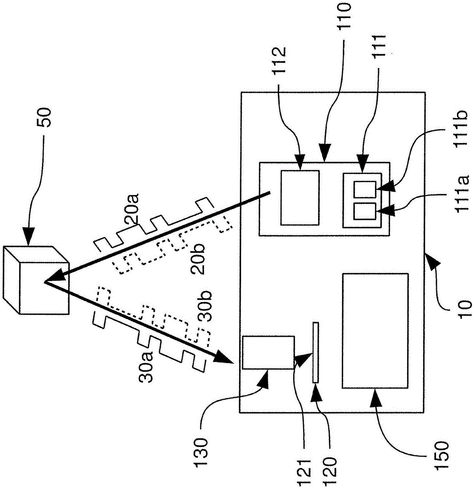
[0043] figure 1 Block diagrams of embodiments of apparatus and methods are shown. The structured light imaging system 10 includes a light projector 110 , an image sensor 120 , an optical system 130 , and a controller 150 for acquiring images of objects 50 in a scene. Opt...


PUM


Abstract

The present invention relates to a structured light imaging system and method. The structured light imaging system and method is adapted to include a projector with at least two groups of light emitters and an image sensor with an array of pixel, wherein a controller is configured to enable that each group is operated individually. In a variant, each pixel of the image sensor allocates one storage node to each of the at least two group of light emitters.

Description

technical field [0001] The present invention relates to imaging systems and methods, and more particularly, to structured light imaging systems and methods. The invention also relates to a method and a device for determining a depth map of a scene. Background technique [0002] Many depth sensing measurement systems (also known as 3D imaging systems or 3D cameras) rely on the principle of triangulation. One of the most common approaches in active triangulation systems utilizes a transmitter (or projector) and receiver, which are physically separated from each other to establish the baseline length of the triangulation system. Projectors provide structured lighting. Structured lighting is understood here as a spatially coded or modulated lighting. The receiver contains an image sensor with an array of pixels. The controller typically processes the raw images obtained by the receiver and derives a three-dimensional depth map of the obtained object, scene or person. Such s...

Claims


Application Information

Patent Timeline
Patent Type & Authority Applications(China)
IPC IPC(8): G01B11/25
CPCG01B11/2513H04N13/20H04N13/128H04N13/296H01S5/423H04N25/75H04N2013/0081
Inventor T·欧吉尔
Owner HEPTAGON MICRO OPTICS