Non-contact probe control interface

a control interface and probe technology, applied in the direction of resistance/reactance/impedence, distance measurement, instruments, etc., to achieve the effect of simple implementation and decoding schem

Active Publication Date: 2010-01-26
MITUTOYO CORP
View PDF24 Cites 112 Cited by
  • Summary
  • Abstract
  • Description
  • Claims
  • Application Information

AI Technical Summary

Benefits of technology

[0009]In accordance with another aspect of the invention, the number of connections on an autojoint for the probe are made to be consistent with existing systems. For example, existing Renishaw type systems typically have standard connections with a standard number of pins (e.g. 13 pins). By providing an autojoint with standardized connections, existing systems can be upgraded more easily.
[0010]In accordance with another aspect of the invention, the spatial light modulator patterns are able to be modified. This allows for the utilization of existing spatial light modulator signals in existing systems, while providing additional information for the control signals for the other elements of the non-contact probe.
[0011]In accordance with another aspect of the invention, a variety of spatial light modulator patterns, ranging from coarse to fine, are projected on each portion of the workpiece surface that is to be measured. The finer patterns are intended to generally provide more accurate measurements, while the coarser patterns help avoid phase ambiguity and provide reference points that are more easily discerned. In general, each of the patterns comprises a series of stripes that cover a patch of the workpiece. A camera is placed at an angle with regard to the surface, so that the stripes appear as contour lines. The offset portions of the contour lines are indicative of raised surface features (as opposed to a straight line which would be indicative of a flat surface). The offset portions are therefore indicative of the Z-height of the surface features on the workpiece, which can be calculated in accordance with a triangulation formula, as determined in part by the angular orientation and distance of the camera relative to the nominal projection plane on which the pattern appears. The information from each of the contour stripes can then be accurately recombined to produce a 3-D surface map for the measured surface of the workpiece. By utilizing a series of such patterns which range from coarse to fine, the rough locations of surface features can be determined by the coarser patterns, while more accurate measurement data may be determined with the finer patterns. If only the finer patterns were utilized, in some embodiments confusion might result in the obtained image data with regard to which line of the pattern was being viewed. By using coarser patterns, the system is more accurately able to determine which line of the pattern is being viewed, and thus rough locations of surface features may be determined, after which the finer patterns may be utilized to obtain more accurate measurement data with regard to the surface features.
[0012]In accordance with another aspect of the invention, the laser of the system is controlled to provide sufficient energy to illuminate a variety of workpieces. In combination with the laser, a rotating diffuser is utilized to avoid speckle patterns which could otherwise reduce the accuracy of the system.

Problems solved by technology

If only the finer patterns were utilized, in some embodiments confusion might result in the obtained image data with regard to which line of the pattern was being viewed.

Method used


Image

  • Non-contact probe control interface
  • Non-contact probe control interface
  • Non-contact probe control interface

Examples


Embodiment Construction

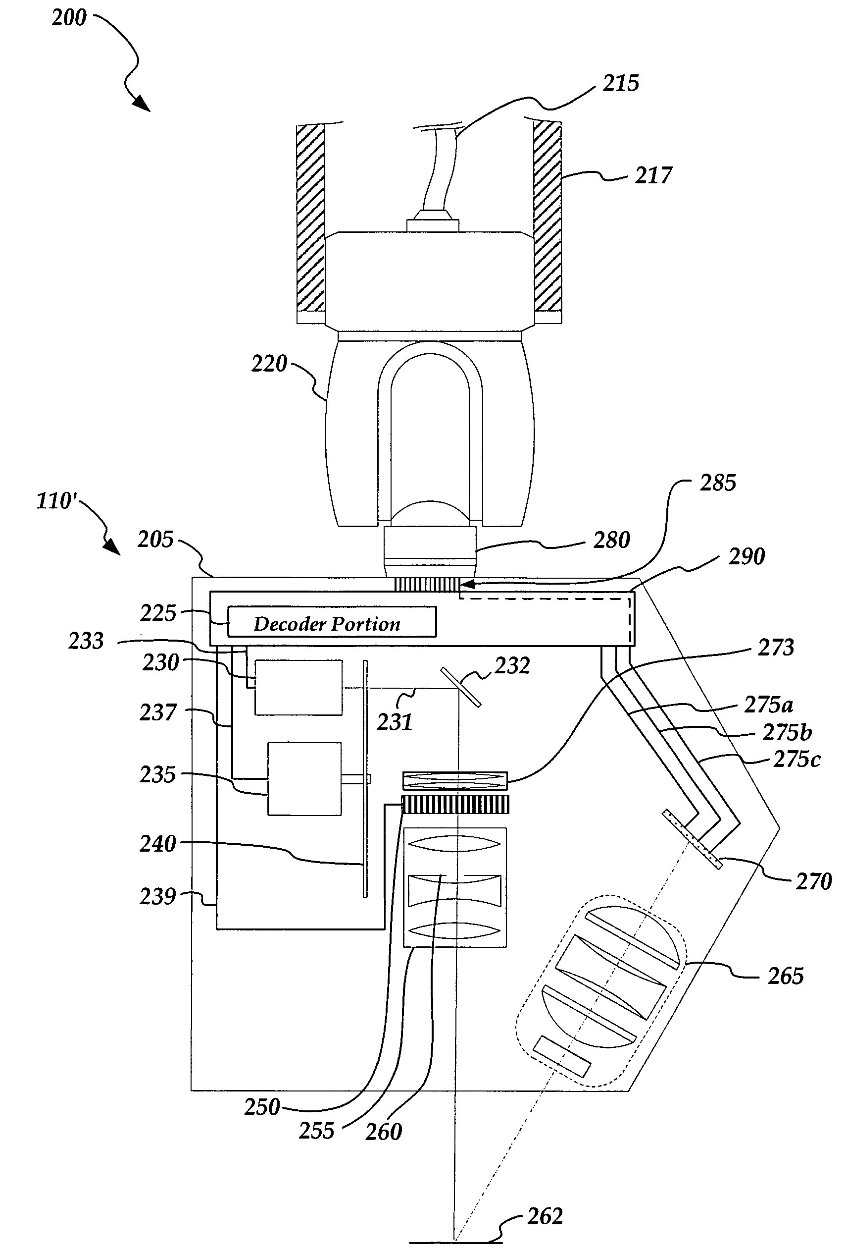
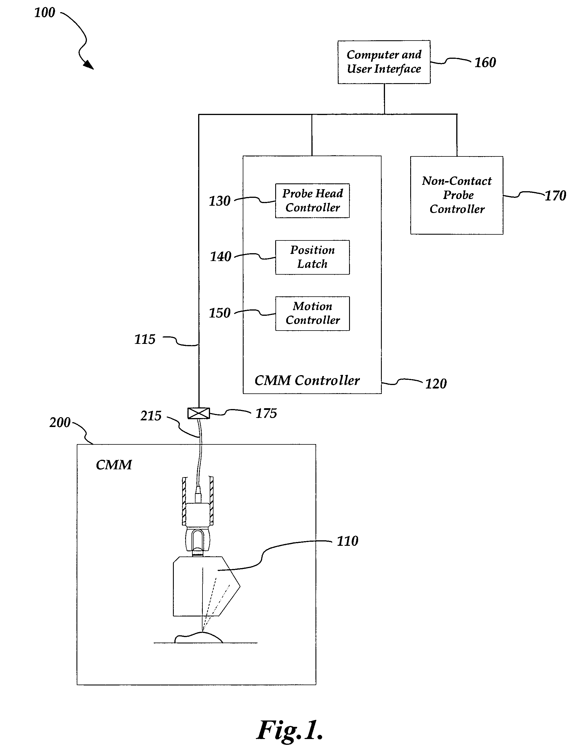
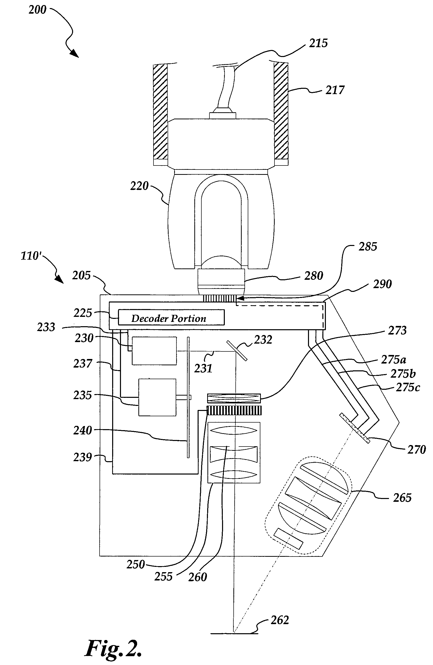
[0024]FIG. 1 is a diagram of a coordinate measurement system 100. The coordinate measurement system 100 includes a coordinate measurement machine controller 120, a computer and user interface 160, a probe controller 170 and a coordinate measurement machine 200. The controller 120 includes a probe head controller 130, a position latch 140 and a motion controller 150. The coordinate measurement machine 200 includes a non-contact structured light probe 110.

[0025]The coordinate measurement machine 200 communicates with all of the other components through a data transfer line 115 (e.g. a bus), which is connected by a connector 175 (e.g. a “micro-D” type connector) to a probe head cable 215 which provides signals to and from the non-contact structured light probe 110. The coordinate measurement machine 200 is controlled by the coordinate measurement machine controller 120, while the non-contact structured light probe 110 is controlled by the probe controller 170. The user may control all ...


PUM

PropertyMeasurementUnit
poweraaaaaaaaaa
depth of fieldaaaaaaaaaa
impedanceaaaaaaaaaa

Abstract

A probe control interface is provided for a structured light non-contact coordinate measuring machine probe. Portions of a video control signal for controlling the grey level of selected rows of pixels of a spatial light modulator of the probe can be decoded into control signals for additional probe components or functions that have been added to increase the measuring capabilities or versatility of the non-contact probe. By providing the additional probe component control signals in this manner, a versatile structured light non-contact probe system can be made compatible with a standard probe head autojoint system (e.g. a Renishaw™ type system), thus allowing the probe to be automatically exchanged with other standard probes and allowing existing systems to use the non-contact probe more easily. Various aspects of the probe control interface allow for relatively simple, compact, lightweight and robust implementation.

Description

FIELD OF THE INVENTION[0001]The invention relates generally to precision measurement instruments, and more particularly to a non-contact probe control interface that is used in a coordinate measuring machine.BACKGROUND OF THE INVENTION[0002]In one type of coordinate measuring machine, the surface of a workpiece is scanned with a probe. After the scan, a three dimensional profile of the workpiece is provided. In one type of scanning probe, the workpiece is directly measured by touching a mechanical contact of the probe to various points along the workpiece surface. In some cases, the mechanical contact is a ball.[0003]In other coordinate measuring machines, an optical probe is utilized which measures the workpiece without making physical contact with the surface. Certain optical probes utilize light points (such as triangulation probes), as well as mostly so-called video probes, which comprise video cameras which detect a greater portion of the workpiece surface. In some systems, the...

Claims


Application Information

Patent Timeline
Patent Type & Authority Patents(United States)
IPC IPC(8): G01N21/86G01C3/08G01R27/26
CPCG01B11/007G06T7/521G01B11/25
Inventor GLADNICK, PAUL
Owner MITUTOYO CORP
Why Eureka
Try Eureka