Object detection system

a technology of object detection and range finder, which is applied in the field of range finder and collision avoidance system, can solve the problems of falling branches, parked cars, and tools and machinery left in the wrong place, and achieve the effect of convenient self-navigating domestic robots

Inactive Publication Date: 2007-01-25
SINCLAIR KENNETHH +2
View PDF6 Cites 106 Cited by
  • Summary
  • Abstract
  • Description
  • Claims
  • Application Information

AI Technical Summary

Benefits of technology

[0018] It is an object of the present invention to provide a mechanically robust, inexpensive method and apparatus for obstacle detection for use on autonomous vehicles. It is a further object of the present invention to provide an inexpensive optical security device capable of detecting unwanted movement or presence of objects within a monitored volume of space. It is a further object of the present invention to provide an inexpensive, mechanically robust, reliable vehicle collision avoidance system. It is a further object of the present invention to facilitate inexpensive self-navigating domestic robots.

Problems solved by technology

One of the major challenges facing the designers of autonomous agricultural machinery is the design of systems which allow autonomous machinery to intelligently navigate from place to place in real-world environments.
Unfortunately, unexpected changes to the environment occur frequently in the real world.
In an agricultural environment, unexpected obstacles that might be encountered include parked cars, tools and machinery left in the wrong place, barrels, and fallen branches.

Method used


Image

  • Object detection system
  • Object detection system
  • Object detection system

Examples


Embodiment Construction

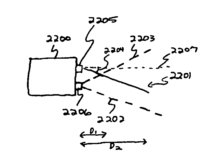
[0028] In FIG. 21 an autonomous vehicle 2100 is equipped with the present invention. Forward-looking downward-angled light beam 2102 is emitted from beam source 2101. Light beam 2102 vertically traverses the field of view of forward-looking video camera 2109. If light beam 2102 intersects some object at distance D1 (from the front of autonomous vehicle 2100) and height H1, a spot 2110 is seen in the field of view of camera 2109. If light beam 2102 intersects some object tat distance D2 and height H2, a spot 2111 is seen in the field of view of camera 2109. If light beam 2102 intersects some object at distance D3 and height H3, a spot 2112 is seen in the field of view of camera 2109. If light beam 2102 intersects some object at distance D4 and height H4, a spot 2113 is seen in the field of view of camera 2109. If light beam 2102 intersects the ground at distance D6 from the front of autonomous vehicle 2100, a spot 2114 is seen in the field of view of camera 2109.

[0029] Video camera ...


PUM


Abstract

An object detection system utilizing one or more thin, planar structured light patterns projected into a volume of interest, along with digital processing hardware and one or more electronic imagers looking into the volume of interest. Triangulation is used to determine the intersection of the structured light pattern with objects in the volume of interest. Applications include navigation and obstacle avoidance systems for autonomous vehicles (including agricultural vehicles and domestic robots), security systems, and pet training systems.

Description

[0001] This application claims priority to provisional patent application No. 60 / 463,525, filed Apr. 17, 2003.FIELD OF THE INVENTION [0002] The field of the invention relates range finders, collision avoidance systems, automated object detection systems, optical proximity detectors, and machine vision. BACKGROUND OF THE INVENTION [0003] As technology has advanced over the years, more and more automated means have been developed to do tasks which were originally accomplished by human beings. Indeed, automation and machinery have made possible the accomplishment of many things which human beings could not do without automation and machinery. At one level, tasks have been automated by making special-purpose machines and / or special-purpose software which do particular tasks. At another level, machines and software have been designed which automate the running of other machines and software. [0004] One of the frontiers of modern automation is the automation of tasks which have traditiona...

Claims


Application Information

Patent Timeline
Patent Type & Authority Applications(United States)
IPC IPC(8): G01C3/08G06K9/00G01B11/14G05D1/02G06V10/145
CPCG01C3/08G01S17/48G01S17/89G01S17/936G05D1/0214G05D1/0248G06K9/00805G05D2201/0201G05D2201/0203G05D2201/0215G06K9/2036G08G1/161G05D1/0274G01S17/931G06V20/58G06V10/145
Inventor SINCLAIR, KENNETHHGAINSBORO, JAY LORINGWEINSTEIN, LEE
Owner SINCLAIR KENNETHH
Why Eureka
Try Eureka