Stator assembling method and stator

An assembly method and stator technology are applied in the direction of electromechanical devices, electric components, prefabricated windings embedded in motors, etc., to achieve the effect of shortening the axial dimension

Active Publication Date: 2017-05-10
AISIN AW CO LTD
View PDF6 Cites 2 Cited by
  • Summary
  • Abstract
  • Description
  • Claims
  • Application Information

AI Technical Summary

Problems solved by technology

Therefore, if the coil shape before being mounted on the stator core is designed without considering the coil shape after being mounted on the stator core, even if the height of the coil end of each turn in the coil shape before mounting is designed to shorten the axial dimension There is also a problem that the apex of the coil on the inner diameter side is higher than the specified height after insertion.

Method used


Image

  • Stator assembling method and stator
  • Stator assembling method and stator
  • Stator assembling method and stator

Examples


Embodiment Construction

[0030] Hereinafter, each embodiment will be described in detail with reference to the drawings.

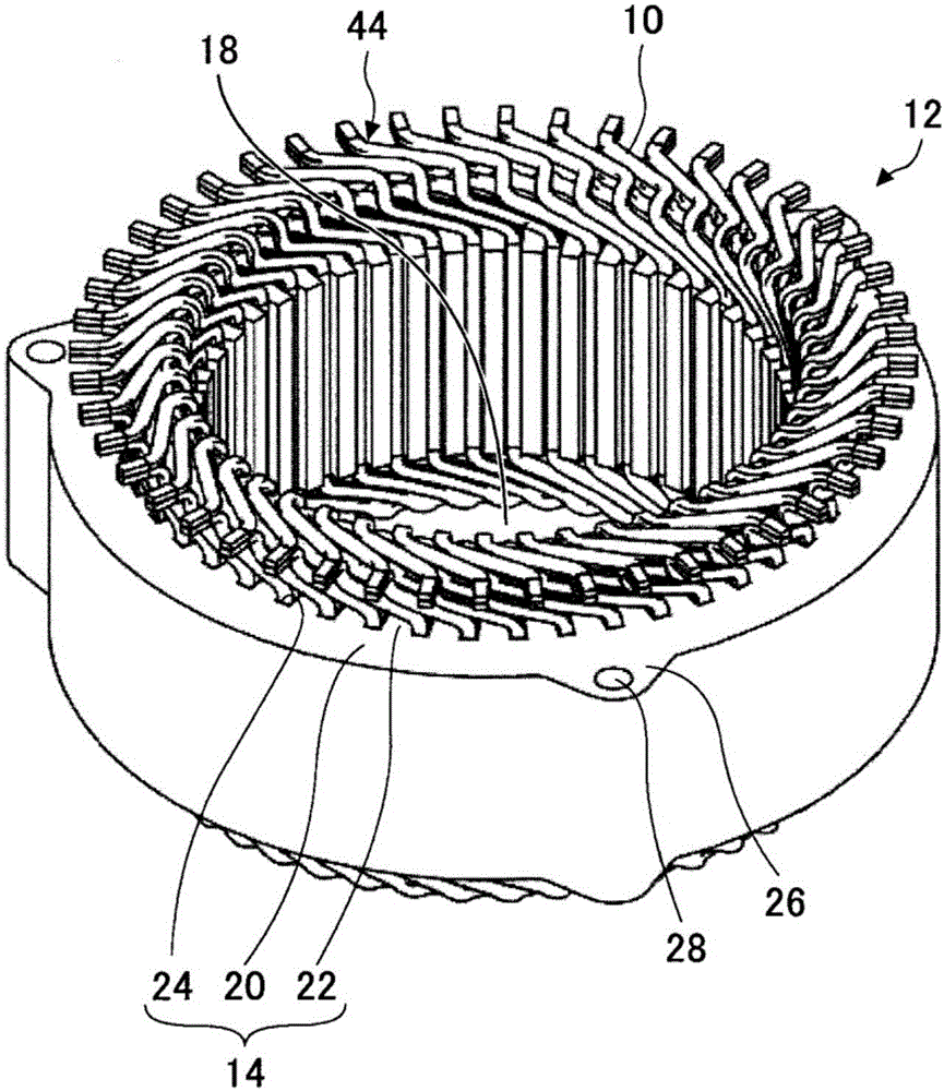
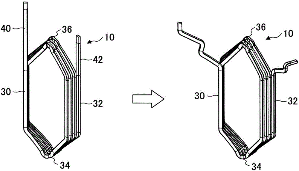
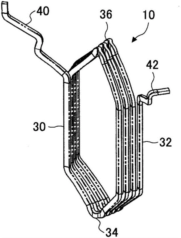
[0031] figure 1 A configuration diagram showing an example of a flat wire concentric winding 10 to which the stator assembling method of the present invention is applied. figure 2 The perspective view showing the lead wire part of the flat wire concentric winding 10 of this embodiment before and after bending processing. Figure 3A as well as Figure 3B It is a figure which shows the state before the flat wire concentric winding 10 of this embodiment is attached to a stator core. exist Figure 3A The perspective view is shown in the Figure 3B 3 shows a front view when viewed from the stator shaft center side in the radial direction, a view when viewed from the stator axial side, and a view when viewed from the stator circumferential side. Figure 4A ~ Figure 4B It is a figure which shows the positional relationship of the two flat wire concentric windings 10 adjacent to the...


PUM


Abstract

Provided is a stator assembling method of mounting, to an annular stator core, concentrically wound coils which are each formed by a conductive wire wound in multiple turns and which each include portions to be accommodated in slots and portions to constitute coil ends, the annular stator core including slots which are formed between adjoining teeth each extending radially inward from a back yoke and are formed such that the spacing of the slots increases toward the radially outward portion. The method includes a step for forming a coil assembly that includes multiple concentrically wound coils disposed annularly, and a step for pushing the coil assembly disposed in a space at the inner-diameter side of the stator core toward the outer-diameter side, and fitting the coil assembly into the slots of the stator core. The multiple concentrically wound coils each have vertices at the portions to constitute coil ends, the vertices being directed axially outward. The distance in the axial direction between the vertices of the portions to constitute coil ends at both sides in the axial direction of the multiple concentrically wound coils is set so as to become gradually shorter from the conductive wire mounted at the outer-diameter side of the stator core to the conductive wire mounted at the inner-diameter side of the stator core.

Description

technical field [0001] The present disclosure relates to stator assembly methods and stators. Background technique [0002] Conventionally, a stator assembly method is known in which a plurality of coils are mounted on a stator core having a plurality of slots each having an opening opening toward the inner periphery (for example, refer to Patent Document 1). Each coil described in this Patent Document 1 is formed by winding a winding wire made of flat wire a plurality of times. Each coil has a side portion inserted into the slot, and a coil end continuous to the side portion. In this stator assembly method, the above-mentioned coil is arranged in a space vacated in the center of the stator core before being attached to the stator core, and then, after the arrangement, the side parts are inserted into the slots of the stator core. Press in a radial manner from the inner diameter side to the outer diameter side. During this pressing, each coil deforms so that the space bet...

Claims


Application Information

Patent Timeline
IPC IPC(8): H02K3/04H02K15/06
CPCH02K3/12H02K15/066H02K3/04H02K15/06H02K3/28H02K15/0435
Inventor 桥本伸吾佐藤真吾岩月和也古贺清隆平原弘次
Owner AISIN AW CO LTD
Why Eureka
Try Eureka