Optical lens, camera module and electronic equipment

An optical lens and lens technology, applied in optics, optical components, instruments, etc., can solve problems such as the inability to achieve clear imaging of distant scenes, the large size limit of the camera module, and the inability of the camera module to achieve high-quality imaging. The effect of miniaturization, reduction of axial dimension, and mitigation of direction change

Pending Publication Date: 2022-01-11
JIANGXI JINGCHAO OPTICAL CO LTD
View PDF0 Cites 0 Cited by
  • Summary
  • Abstract
  • Description
  • Claims
  • Application Information

AI Technical Summary

Problems solved by technology

Due to the thickness limitation of electronic equipment, the size of the camera module is relatively large, and the camera module cannot achieve high-quality imaging. At the same time, the camera module cannot achieve clear imaging of distant scenery

Method used


Image

  • Optical lens, camera module and electronic equipment
  • Optical lens, camera module and electronic equipment
  • Optical lens, camera module and electronic equipment

Examples


no. 1 example

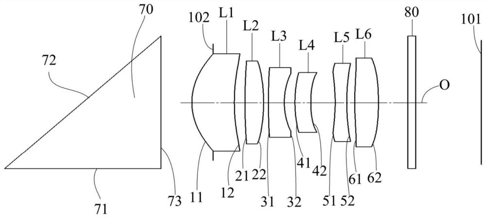
[0097] The structural diagram of the optical lens 100 disclosed in the first embodiment of the present application is as follows figure 1 As shown, the optical lens 100 is arranged in sequence from the object side to the image side along the optical axis O. L5, the sixth lens L6 and the infrared filter 80, wherein the rectangular prism 70 and the infrared filter 80 are made of glass, and the first lens L1 to the sixth lens L6 are made of plastic.

[0098] Further, the first lens L1 has a positive refractive power, the second lens L2 has a positive refractive power, the third lens L3 has a negative refractive power, the fourth lens L4 has a negative refractive power, the fifth lens L5 has a negative refractive power, and the sixth lens L3 has a negative refractive power. Lens L6 has positive refractive power. The object side 11 and image side 12 of the first lens L1 are respectively convex and concave at the optical axis O, and the object side 11 and image side 12 of the first...

no. 2 example

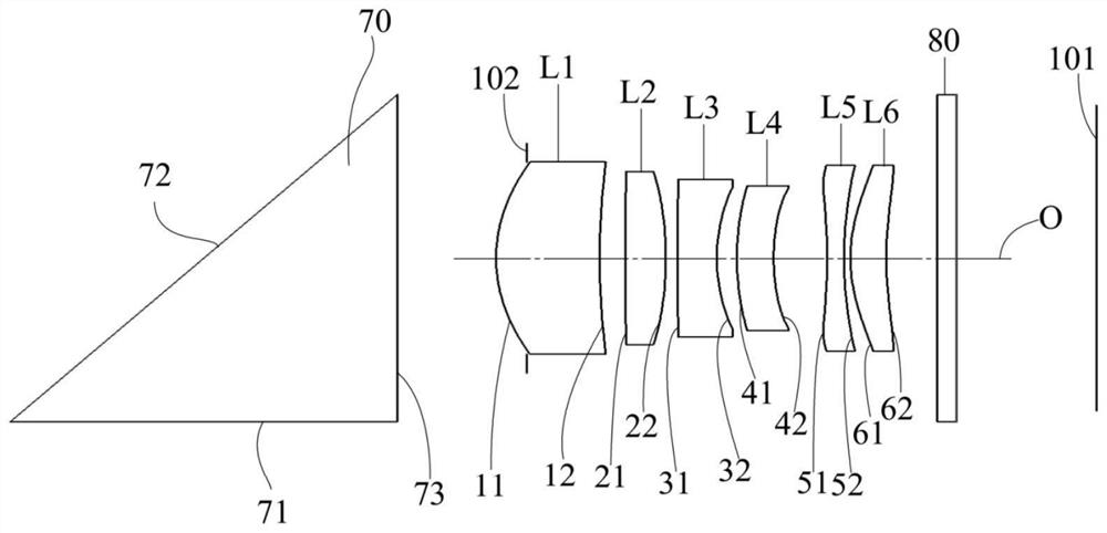
[0111] The structural diagram of the optical lens 100 disclosed in the second embodiment of the present application is as follows image 3 As shown, the optical lens 100 is arranged in sequence from the object side to the image side along the optical axis O. L5, the sixth lens L6 and the infrared filter 80, wherein the rectangular prism 70 and the infrared filter 80 are made of glass, and the first lens L1 to the sixth lens L6 are made of plastic.

[0112] Further, the first lens L1 has a positive refractive power, the second lens L2 has a positive refractive power, the third lens L3 has a negative refractive power, the fourth lens L4 has a negative refractive power, the fifth lens L5 has a negative refractive power, and the sixth lens L3 has a negative refractive power. Lens L6 has positive refractive power. The object side 11 and image side 12 of the first lens L1 are respectively convex and concave at the optical axis O, and the object side 11 and image side 12 of the firs...

no. 3 example

[0121] The structural diagram of the optical lens 100 disclosed in the third embodiment of the present application is as follows Figure 5 As shown, the optical lens 100 is arranged in sequence from the object side to the image side along the optical axis O. L5, the sixth lens L6 and the infrared filter 80, wherein the rectangular prism 70 and the infrared filter 80 are made of glass, and the first lens L1 to the sixth lens L6 are made of plastic.

[0122] Further, the first lens L1 has a positive refractive power, the second lens L2 has a positive refractive power, the third lens L3 has a negative refractive power, the fourth lens L4 has a negative refractive power, the fifth lens L5 has a negative refractive power, and the sixth lens L3 has a negative refractive power. Lens L6 has positive refractive power. The object side 11 and image side 12 of the first lens L1 are respectively convex and concave at the optical axis O, and the object side 11 and image side 12 of the firs...


PUM


Abstract

The invention discloses an optical lens, a camera module and electronic equipment, and the optical lens comprises,in order from an object side to an image side along an optical axis,a first lens element with positive refractive power, whereinan object-side surface and an image-side surface of the first lens element lens element are convex and concave in a paraxial region; a second lens element with positive refractive power, wherein an object-side surface and an image-side surface of the second lens element are convex in a paraxial region. a third lens element with negative refractive power; a fourth lens element with refractive power, wherein a concave image-side surface of the fourth lens element is in a paraxial region. a fifth lens element with negative refractive power, wherein both the object-side and image-side surfaces thereof are concave in a paraxial region; and a sixth lens element with positive refractive power, wherein the optical lens satisfies the following relational expression: FOV / TTL is greater than 1 deg / mm and less than 4 deg / mm. According to the optical lens, the camera module and the electronic equipment provided by the embodiment of the invention, high-quality imaging of distant sceneries can be realized while the design requirement of miniaturization is met.

Description

technical field [0001] The invention relates to the technical field of optical imaging, in particular to an optical lens, a camera module and electronic equipment. Background technique [0002] As the public's miniaturization requirements for electronic equipment (such as mobile phones, tablet computers, telephone watches, etc.) The camera function of the electronic equipment, the camera module is an indispensable component in the existing electronic equipment. In order to meet the demand for miniaturization of electronic equipment, the size of the camera module tends to be more miniaturized. Due to the limitation of the thickness of the electronic equipment, the size of the camera module is relatively large, the camera module cannot achieve high-quality imaging, and at the same time, the camera module cannot achieve a clear imaging effect on distant objects. Contents of the invention [0003] The embodiment of the invention discloses an optical lens, a camera module, an...

Claims


Application Information

Patent Timeline
IPC IPC(8): G02B13/00G02B13/18
CPCG02B13/0015G02B13/0045G02B13/0065G03B30/00
Inventor 刘彬彬邹海荣李明
Owner JIANGXI JINGCHAO OPTICAL CO LTD
Why Eureka
Try Eureka