
Cleaning device for transmission shaft system

A technology for cleaning devices and transmission shafts, which can be applied to cleaning methods using tools, cleaning methods and utensils, chemical instruments and methods, etc., and can solve problems such as delays in construction periods.

Active Publication Date: 2017-05-17
WUHAN MARINE MACHINERY PLANT
View PDF7 Cites 4 Cited by
  • Summary
  • Abstract
  • Description
  • Claims
  • Application Information

AI Technical Summary

Problems solved by technology

[0005] In order to solve the problem that the cleaning of the transmission shaft will delay the construction period, the embodiment of the present invention provides a cleaning device for the transmission shaft

Method used


Image

  • Cleaning device for transmission shaft system
  • Cleaning device for transmission shaft system
  • Cleaning device for transmission shaft system

Examples


Embodiment

[0031] An embodiment of the present invention provides a cleaning device for a transmission shaft system. The transmission shaft system is a common power transmission mechanism in construction machinery, and mainly includes a support structure and a transmission shaft. The transmission shaft is rotatably mounted on the support structure, thereby The transmission shaft can be effectively supported by the support structure.

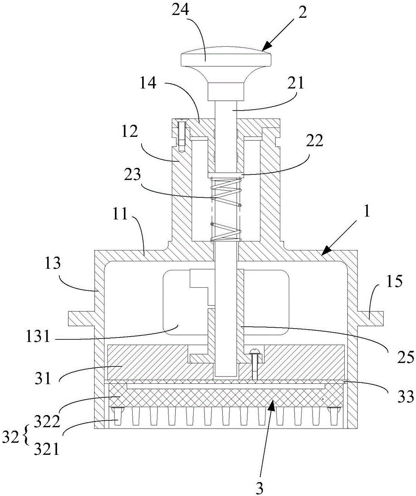
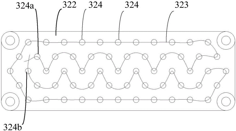
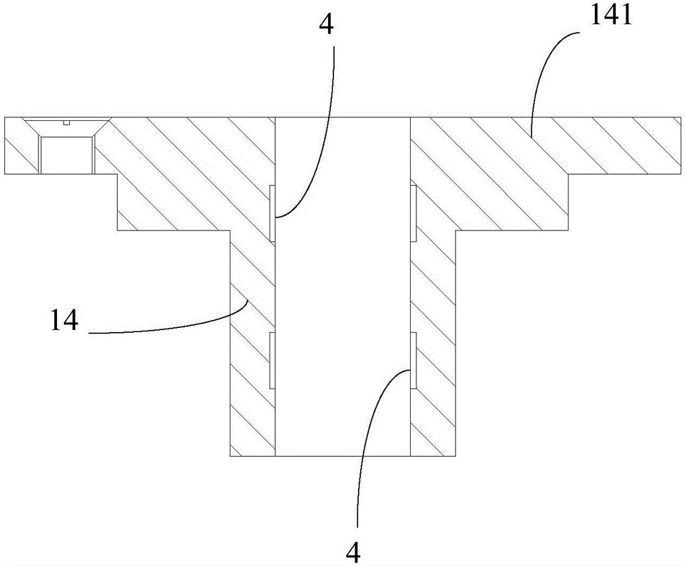
[0032] In this example, if figure 1 As shown, the cleaning device includes: a housing 1, an operating assembly 2 and a cleaning assembly 3, the housing 1 is fixedly installed on a support structure, and the housing 1 includes an end plate 11, a first cylinder 12, a second cylinder 13 and Limiting sleeve 14, one end of the first cylindrical body 12 is vertically fixed on one side of the end plate 11, the limiting sleeve 14 is fixedly installed on the other end of the first cylindrical body 12, and one end of the second cylindrical body 13 is vertically fixed...


PUM


Abstract

The invention discloses a cleaning device for a transmission shaft system, and belongs to the field of cleaning devices. The cleaning device comprises a shell body, an operating assembly and a cleaning assembly. The shell body comprises an end plate, a first cylinder body, a second cylinder body and a limiting shaft sleeve. One end of the first cylinder body is vertically fixed on one side of the end plate; the limiting shaft sleeve is inserted in the other end of the first cylinder body; and one end of the second cylinder body is vertically fixed on the other side of the end plate. The operating assembly comprises a sliding shaft, a limiting ring and an elastic piece. One end of the sliding shaft sequentially penetrates through the limiting shaft sleeve and the end plate and is slidably inserted in the shell body. The limiting ring is coaxially arranged on the sliding shaft and located in the first cylinder body; one side of the limiting ring abuts against the limiting shaft sleeve; and the elastic piece is clamped between the other side of the limiting ring and the end plate. The cleaning assembly is located in the second cylinder body and comprises a mounting seat and a cleaning brush. The cleaning brush is fixedly mounted on one side of the mounting seat, and the other side of the mounting seat is fixedly connected with one end of the sliding shaft. The transmission shaft system in working can be cleaned through the cleaning device.

Description

technical field [0001] The invention belongs to the field of cleaning devices, and in particular relates to a cleaning device for a transmission shaft system. Background technique [0002] The transmission shaft system is a very common mechanism in construction machinery, mainly including a support structure, a transmission shaft and a sensor, etc. The transmission shaft is rotatably installed on the support structure to support the transmission shaft, and the sensor is arranged on the support structure for Detect various working parameters of the transmission shaft. [0003] During the working process of the transmission shaft system, some dust and oil particles will inevitably adhere to the transmission shaft, and long-term accumulation will form pollution on the outer surface of the transmission shaft, resulting in inaccurate sensor readings. In order to solve the above problems, workers are usually required to use a cleaning brush to regularly stop and clean the transmi...

Claims


Application Information

Patent Timeline
Patent Type & Authority Applications(China)
IPC IPC(8): B08B1/02B08B13/00
CPCB08B13/00B08B1/12B08B1/20
Inventor 潘文鼎佘邵平贾广营李亚曾庆飞严国辉张明陈英
Owner WUHAN MARINE MACHINERY PLANT
Learn More