Horizontal grooving machine combined roller core device

A rolling grooving machine and combined technology, applied in the direction of feeding device, positioning device, peeling device, etc., can solve the problems of stuck battery, affecting the output pass rate, and battery throwing away, so as to improve the quality of sealing and improve production Efficiency and output pass rate, the effect of reducing the flare diameter

Active Publication Date: 2019-06-14
HENGYANG BST POWER
View PDF10 Cites 0 Cited by
  • Summary
  • Abstract
  • Description
  • Claims
  • Application Information

AI Technical Summary

Problems solved by technology

[0003] 1. After the battery flaring diameter is enlarged, it will be difficult to close the battery when sealing, thus improving the sealing quality;
[0004] 2. The battery will fall off on the roller core, so that the next battery cannot enter and the battery will be damaged, which will affect the output pass rate;
[0005] 3. Batteries are thrown off by the centrifugal force of the roller core rotation, and individual batteries will be thrown off, which will affect production efficiency

Method used


Image

  • Horizontal grooving machine combined roller core device
  • Horizontal grooving machine combined roller core device
  • Horizontal grooving machine combined roller core device

Examples


Embodiment Construction

[0019] In order to make the technical means, creative features, objectives and effects achieved by the present invention easy to understand, the present invention will be further elaborated below.

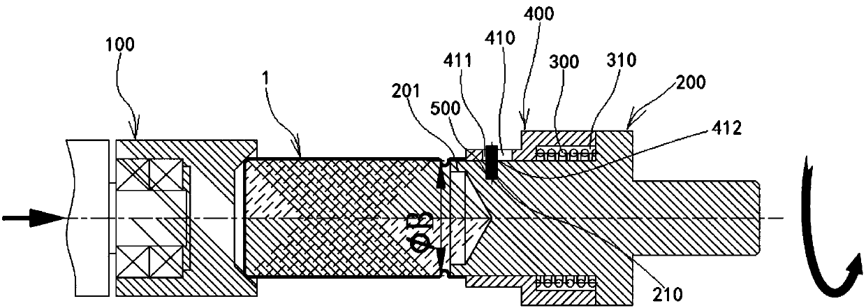
[0020] see image 3 and Figure 4 The combined rolling core device of the horizontal rolling groove machine shown includes a top core 100 and a rolling core 200 , and a telescopic sleeve 400 is provided on the outer peripheral surface of the processed end surface 201 of the rolling core 200 through an elastic member 300 .

[0021] In this embodiment, the inner wall of the telescopic sleeve 400 and the outer peripheral surface of the roller core 200 form a limiting cavity 310 that jointly limits the expansion and contraction of the elastic member 300 . The roller core 200 is provided with a limiting pin hole 210 , and the telescopic sleeve 400 is provided with a limiting groove 410 corresponding to the limiting pin hole 210 , and a limiting pin 500 passes through the limiting pin h...


PUM


Abstract

The invention discloses a combined rolling core device of a horizontal grooving machine. When the battery is directly pushed into the processed end face of the roller core, the telescopic sleeve is squeezed by the end face of the battery and compressed to the shrinking station; The inner ejection of the roller core. The beneficial effects of the present invention are as follows: 1. After the top core is withdrawn after the battery is punched, the battery is ejected from the core by the spring in the core to ensure that the battery can completely fall off from the core, thereby improving production efficiency and output pass rate. 2. It can reduce the flaring diameter of the battery when punching the groove, thereby improving the sealing quality of the battery.

Description

technical field [0001] The invention relates to the field of horizontal grooving machines, in particular to a combined roller core device of a horizontal grooving machine. Background technique [0002] see figure 1 and figure 2 As shown, when the current horizontal grooving machine rolls the battery, it mainly uses the top core 10 and the rolling core 20 to cooperate. Before the battery 30 is grooved, the battery 30 is directly pushed into the rolling core by the thrust of the top core 10 20 in ФB; and then punch the slot; when the battery 30 is punched, the top core 10 shrinks back, and the battery 30 expands the diameter of the battery flare ФC, and then the tail of the battery 30 is drooped by its own weight, and then the roller core The centrifugal force of the rotation of 20 is dropped. This production method has the following problems: [0003] 1. After the battery flaring diameter is enlarged, it will be difficult to close the battery when sealing, thus improving...

Claims


Application Information

Patent Timeline
Patent Type & Authority Patents(China)
IPC IPC(8): B21D17/04B21D43/00B21D45/10H01M10/04H01M6/00
CPCB21D17/04B21D43/003B21D45/10H01M6/005H01M10/0404Y02P70/50
Inventor 贺炳富
Owner HENGYANG BST POWER
Why Eureka
Try Eureka