
Bearing detachment device

A bearing dismounting device and bearing technology, which are applied in the field of bearing assembly, can solve the problems of unbalanced force, affecting the quality of aero-engines, and the inability to disassemble bearings of different models and sizes, so as to ensure the effect of bearing force

Active Publication Date: 2017-05-17
CHINA HANGFA SOUTH IND CO LTD
View PDF8 Cites 6 Cited by
  • Summary
  • Abstract
  • Description
  • Claims
  • Application Information

AI Technical Summary

Problems solved by technology

[0004] The invention provides a bearing dismounting device to solve the problem of unbalanced bearing force during dismounting, scratching the main shaft, leaving disassembly traces on adjacent fittings and affecting the quality of the aeroengine, and dismounting device cannot disassemble bearings of different sizes. technical problem

Method used


Image

  • Bearing detachment device
  • Bearing detachment device
  • Bearing detachment device

Examples


Embodiment Construction

[0029] It should be noted that, in the case of no conflict, the embodiments in the present application and the features in the embodiments can be combined with each other. The present invention will be described in detail below with reference to the accompanying drawings and examples.

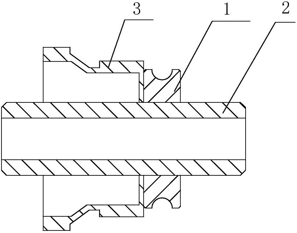
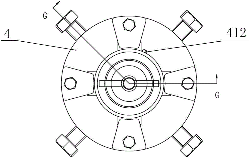
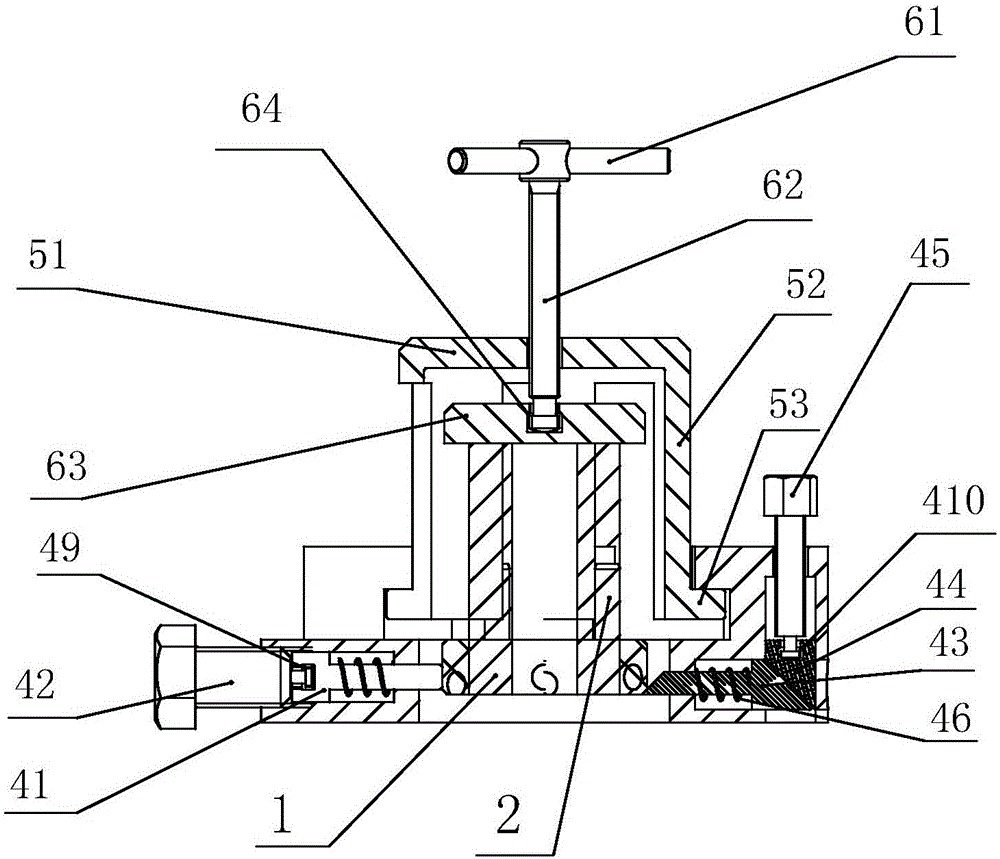
[0030] refer to figure 1 , figure 2 , image 3 , the preferred embodiment of the present invention provides a bearing dismounting device, the base 4 that tightens the bearing 1 and drives the movement of the bearing 1, and the traction mechanism 5 that connects the base 4, and the base 4 includes circumferentially evenly distributed Centering mandrel 41, centering mandrel 41 is connected and is used to promote its motion to be suitable for clamping the first screw rod 42 of bearing 1 of different size, and first screw rod 42 is screwed on the base 4; Traction mechanism 5 is connected by thread. The rotating mechanism 6 drives the traction mechanism 5 to move through the reaction of the thre...


PUM


Abstract

The invention discloses a bearing detachment device. The bearing detachment device comprises a base used for abutting and clamping bearings and driving the bearings to move, and a traction mechanism connected with the base, wherein the base comprises alignment mandrels used for abutting and clamping the bearings and uniformly distributed in the circumferential direction, the alignment mandrels are connected with a first screw rod used for pushing the alignment mandrels to move to adapt to clamp the bearings with different dimensions, and the first screw rod is screwed onto the base; and the traction mechanism is connected with a rotation mechanism through a thread, and the rotation mechanism drives the traction mechanism to move through the reaction of the thread. The bearing detachment device is applicable to detachment for the separable angular contact bearings, and capable of meeting the detachment need of the bearings with different types and dimensions through adjusting the dimensions of the base; the stress equilibrium of the bearings is guaranteed, detachment traces left due to partial overload are avoided, and a main shaft is prevented from scratches; and the bearing detachment device can be used for the bearings next to mating parts and is capable of avoiding detachment traces left on the adjacent mating parts.

Description

technical field [0001] The invention relates to the field of bearing assembly, in particular to a bearing dismounting device. Background technique [0002] Bearings are widely used in automobiles, ships, aviation and other fields, including high-speed rotary bodies in these fields, and high-speed rotary bodies have strict requirements on the interference fit of bearings. At this time, the inner ring of the bearing must play a fixed role , and it is necessary to facilitate disassembly during the assembly and debugging process, which has higher requirements for bearing disassembly tools. The aero-engine needs to perform a dynamic balance test on the main shaft of the blade before the test run. This process requires multiple bearing disassembly on the main shaft, but the strict interference fit makes it difficult to disassemble the bearing, and it is easy to scratch the mating parts during the disassembly process. Main shaft; In addition, the size of the force-bearing part tha...

Claims


Application Information

Patent Timeline
Patent Type & Authority Applications(China)
IPC IPC(8): B25B27/073
Inventor 李强张中全张菊绒游丹
Owner CHINA HANGFA SOUTH IND CO LTD
Learn More